Master data collection unit NR-X100W

NR-X100W - Master data collection unit

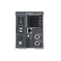
*Please note that accessories depicted in the image are for illustrative purposes only and may not be included with the product.

  • CE Marking
  • CSA

Specifications

Model

NR-X100W

Main unit buffer memory capacity

50M data*1

Expansion memory

SD card (SD/SDHC)*2

PC interface

USB

USB mini-B connector, USB 2.0 High-speed–compliant, Simultaneous USB connection from one PC to up to four units (switchable by ID switch)

Ethernet

RJ45 connector, 100Base-TX (AUTO MDI/MDIX supported) *3

Wireless LAN

Connection via NR-XW1 wireless LAN unit, IEEE 802.11b/g/n *3

Network function

FTP client function, FTP server function, SNTP client function

Display/operation

Operation via NR-XCP30 control panel, or via WAVE LOGGER X with PC connection

Expansion remote unit connection

Dedicated remote connection connector × 2 (Remote OUT A port, B port)
Unit expansion possible by connecting up to eight NR-XR01 remote units (connected by remote unit cable)

Number of connectable measurement units

Master data collection unit group

Max. 8 units*4

Total with remote units connected

Max. 72 units*5

Continuous acquisition speed

Master data collection unit group

Max. 100 kHz for all acquisition channels *6

Total with remote units connected

Max. 500 kHz for all acquisition channels *6*7

Inter-unit synchronization

Between measurement units in the master data collection unit group

±1 μs or less *8

Between the master data collection unit and each remote unit / environment-resistant measurement unit

Time axis accuracy

±50 ppm (23°C ±3°C 73.4°F ±5.4°F); Same time used for all remote groups, SNTP server time synchronization possible

Synchronous trigger input (SYNC input)

Performance specifications

• Use as external trigger input (normal mode) or synchronous acquisition input (logging mode)
• Non-voltage (contact/non-contact)/voltage input, Falling edge input
• Not insulated from system bus

Input specifications

• For non-voltage input: ON voltage 1.0 V or lower (short circuit current: 1 mA typ.), OFF current 0.1 mA or lower
• For voltage input: ON voltage (Lo) 1.0 V or lower, OFF voltage (Hi) 2.4 V or more, Max. input voltage: 6 V

Control input

Common specifications

• Input type: Bidirectional voltage input
• Maximum rating: 30 VDC, Minimum ON voltage: 10 VDC, Maximum OFF current: 0.2 mA
• Insulation between input and system bus (500 VDC/1 minute)

Individual specifications

• External trigger input (TRG IN): Edge input
• Acquisition start/stop input (START IN): Level input (only enabled in external control mode)
• Auto-balance input (BAL): Edge input (only enabled in external control mode)
• Program selection input 0 to 3 (PROG IN0 to 3): Level input (only enabled in external control mode)

Control output

Common specifications

• Output format: Photo MOS relay output
• Maximum rating: 36 VDC, Output current: 50 mA or less (9-point total: 300 mA or less)
• Leak current at OFF: 0.1 mA or less, Residual voltage when ON: 1 V or less
• Insulation between output and system bus (500 VDC/1 minute)

Individual specifications

• Trigger output (TRG OUT): N.O. output, one-shot output
• System error output (SYS ERR): N.C. output
• Alarm output (ALARM): N.O. output
• Judgment output 1 to 4 (OUT1 to 4): N.O. output
• Ready output (READY): N.O. output

Power supply

• NR-XU1 AC adapter, or 9 to 36 VDC (including ripple) / Max. 72 W (when connected to DC terminal block; at 9 V: 8.0 A or less; at 24 V: 3.0 A or less; at 36 V: 2.0 A or less)
• Battery operation possible when connected to the NR-XU15 battery power supply unit

Power supply

Power consumption

8.4 W or less (excluding connected units)

Environmental resistance

Ambient temperature

0 to +40°C 32°F to 104°F

Relative humidity

10 to 85% RH (no condensation)

Weight

Approx. 490 g 17.30 oz (including approx. 10 g 0.35 oz for the OP-88512 (NR-X100W I/O terminal block))

*1 Data is not backed up when the power is turned off. The available data buffer memory per NR-X100W and NR-XR01 group is limited to 25M.
*2 Use only products recommended by KEYENCE (CA-SD4G: 4 GB, CA-SD16G: 16 GB). Using a product not recommended by KEYENCE may result in data not being saved to the SD card during continuous acquisition.
*3 Wired LAN and wireless LAN cannot be used at the same time. When acquiring data from a PC (using WAVE LOGGER X software), use a wired local connection only between the NR-X100W and the PC. Using an onsite local network connection or wireless LAN connection may cause acquisition to stop due to a decrease in transfer speeds caused by network load or wireless LAN communication conditions. The main unit’s automatic saving function allows data to be saved to an SD card in the main unit even if acquisition by PC stops.
*4 Use is permitted only if the total power consumption of all connected measurement units is 20 W or less.
*5 Use is permitted only if the total power consumption of all measurement units, remote units, and environment-resistant measurement units used in the system is 50 W or less when remote units are not connected to an AC adapter.
*6 Acquisition from a PC may not be possible in some PC environments. [Tested conditions] OS: Windows 10 Pro (64 bit), CPU: 3.70 GHz, RAM: 16.0 GB, USB connections: One NR-X100W (no other USB devices), Ethernet connection: One-to-one connection between NR-X100W and PC; Using normal mode and saving in the standard format with a pre-installed OS and running only WAVE LOGGER X. Windows is a registered trademark or a trademark of Microsoft Corporation in the United States and/or other countries.
*7 Each master data collection unit group and remote unit group is limited to 100 kHz for all acquisition channels. When using 5 or more remote units, each remote unit group can have up to 50 kHz per acquisition channel.
*8 The sampling cycle and sampling timing vary depending on the connected measurement unit. When using the NR‑CA04 in combination with other unit types, a sampling delay may occur between the NR-CA04 and the other units with some setting configurations.

Data Sheet (PDF) Other Models