Laser Microscopes
What is a Laser Microscope?

Laser Microscopes incorporate two light sources: a white light for gathering color information, and a laser source for gathering height information. To capture height data, the laser is scanned in the XYZ directions across the surface of the sample, and the reflected light intensity is measured. The result is a high-resolution, large depth-of-field, color image with nanometer-level height resolution for accurate profile and roughness measurements. This equipment combines the functionality of an optical microscope, scanning electron microscope, and surface roughness gauge.
With these devices, there are no size, shape, or material limitations. Observations can be made at room temperature without the need for a vacuum, and operations are easy to perform in a manner similar to optical microscopes. There is no need for pre-processing of samples and it is possible to perform color observation. All of these factors enable quick and accurate analysis of samples. These microscopes can also be used to observe the surface layer, inside, and bottom layer of transparent targets and to measure film thickness.
Benefits of Laser Microscopes

Easy to use interface
Laser microscopes exhibit the same ease of use as optical microscopes.
- Magnified observations are possible at room temperature and without the need for a vacuum.
- Observations do not require pre-processing such as deposition.
- Deep depth of focus.
- 3D shapes can be captured, and color 3D images can be displayed.
- Film thickness of transparent films, such as resists, can be measured.
- High-magnification/high-resolution observation of targets.
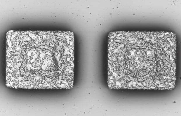
High-contrast images
Laser microscopes obtain high-contrast monochrome images.
- Magnified images can be taken with a deep depth of field.
- Observation can be conducted over a wide range of magnifications.
- Color observation at high magnification is possible.
- Shape measurements are possible. Surface roughness can be quantified as numeric data.
Analyze surface roughness quickly
Laser microscopes can obtain surface roughness measurements as numeric data.
- Non-contact measurement does not damage the sample surface.
- Viscoelastic samples can be measured.
- Measurement point positioning and visual confirmation are possible.
- Small grooves can also be measured.

Laser spot diameter < roughness tester diameter

The laser spot diameter is extremely small, which enables more accurate measurements of detailed shapes.

Standard roughness fragment (Ra = 0.42 μm) measurement example
Principles of Laser Microscopes
Laser microscopes use the confocal principle to detect the height information of the sample.These devices use a point light source, so they capture the surface shape of the area (plane) by using an optical scanner to scan the laser light in the X and Y directions (2D).
The field-of-view is divided into pixels, and the reflected light of each pixel is detected by the light receiving element. A motor is used to move the objective lens or the sample within a fixed range in the vertical direction. During this process, the position information of the objective lens and the amount of light received by the light receiving element are detected at the same time. This makes it possible to detect the focus position of the target from the fluctuation in the amount of received light. The vertical position of the objective lens when the received laser intensity is at a maximum is the height of the measured surface.
Laser microscope structure example
1. Laser light emitted from the laser light source is transmitted through an X-Y scanning optical system, and then scans the sample surface. The receiving element then detects information from the reflected light at the position where the light is focused.
2. The objective lens is moved along the Z-axis , and then the scan is performed again.
3. The above process is repeated for the specified measuring range. Layering the focal position information in the Z-axis direction forms a "fully focused image."
4. By tracking the movement of the objective lens along the Z-axis, the microscope can correlate in focus pixels with height data. The topography of the surface is generated in this way.

The Z-axis position of the objective lens when the amount of reflected light was at maximum (the focal position) and the information for the amount of reflected light (intensity) and the color at this point in time are obtained for each pixel on the surface as shown in the figure on the right. The height-intensity curve on the right allows construction of a high contrast laser intensity image and a 3D height image. A color image with a deep depth of field is obtained with a white-light camera.
Confocal Principle
Laser microscopes utilize a special optical system consisting of a light source, a light receiving element, an objective lens, a half mirror, and a pinhole in order to perform both magnified observation and surface shape analysis. A pinhole placed in front of the light receiving element filters out out-of-focus light and detects only in-focus pixels. Applying this optical system to sensor technology makes it possible to sense the height information of the measurement surface. This detection process is shown in steps (1) to (4) below.

1. Transmission
The laser light generated by the light source is concentrated at the focal point by the objective lens.
A: Light source
B: Objective lens
C: Target
D: Light emitted from the laser is concentrated on the measurement surface by the objective lens.

2. Reflected light
By placing the target at this focal position, the laser light reflected from the surface passes through the objective lens and is focused once more. A pinhole is situated at the focal position. A half mirror is used to change the optical axes such that the light enters the light receiving element.
A: Pinhole
B: Half mirror
C: Light receiving element
D: The reflected light is concentrated on the receiver by the objective lens.

3. Passage of all reflected light
The light focused on the light receiving element passes through the pinhole, and all the reflected light enters the light receiving element.
A: Half mirror
B: Concentrated laser light

4. When out of focus
When the target is at a position that is out of focus, the laser light concentrated by the objective lens is not concentrated to a spot. The reflected laser light is no longer focused on the pinhole, and the laser spot on the pinhole expands. This means that the amount of light that passes through the pinhole and reaches the light receiving element is reduced.
A: The reflected light that enters the hole passes through, but other light is blocked by the mask shaded) part.
B: The light reflected from the target is focused at a position offset from the pinhole in the direction of the optical axis, so the spot expands such that the light is out of focus at the pinhole position.
C: The light concentrated on the target surface spreads out.
A laser microscope detects whether the sample is at the focal position according to the intensity of the reflected light that returns to the light receiving element. An optical system such as this which incorporates a pinhole before the light receiving element is known as a confocal optical system. This detection principle is known as the "confocal principle."