
Air Quality Multi-Sensor
MP-F series
Energy Monitor Main Unit MP-FEA1
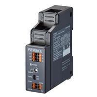
*Please note that accessories depicted in the image are for illustrative purposes only and may not be included with the product.

Specifications
Model | MP-FEA1 | |||
Measurement specifications | Electrical service type | 1-phase 2-wire, 1-phase 3-wire, 3-phase 3-wire, 3-phase 4-wire (switchable) | ||
Number of measurement circuits | 1 (up to 2 circuits with the 1-phase 2-wire setting *1) | |||
Input specifications | Primary-side rated current, In | When using specialized CT MP-FEC100: 100 A Or, general CT (secondary-side rated input current 1 A) *2 | ||
Over current withstand capability | 1.2 times the primary-side rated current (can be applied consecutively), 10 times the primary-side rated current (for 1 second or less) | |||
Rated input voltage | 1-phase 2-wire | ・MP-FEC100/MP-FEC250/MP-FEC600, or general CT in use: 100 to 277 VAC (L-N) | ||
1-phase 3-wire | ・MP-FEC100/MP-FEC250/MP-FEC600, or general CT in use: 100 to 240 VAC (L-N), 200 to 480 VAC (L-L) | |||
3-phase 3-wire | ・MP-FEC100/MP-FEC250/MP-FEC600, or general CT in use: 173 to 480 VAC (L-L) | |||
3-phase 4-wire | ・MP-FEC100/MP-FEC250/MP-FEC600, or general CT in use: 100 to 277 VAC (L-N), 173 to 480 VAC (L-L) | |||
Maximum permissible voltage to earth | ・MP-FEC100/MP-FEC250/MP-FEC600, or general CT in use: 480 VAC to earth | |||
Input voltage fluctuation range | −15% to +15% of the rated input voltage | |||
Rated input frequency | 50/60 Hz | |||
Displayable range/ | Voltage | Display resolution 0.1 [V] | ||
Current | Display resolution 0.001 [A] | |||
Active power/reactive power/apparent power | -8942.400 to +8942.400 [kW/kvar/kVA], display resolution 0.001 [kW/kvar/kVA] | |||
Active energy/reactive energy/apparent energy | 0.000 to 999999.999 [kWh/kvarh/kVAh], display resolution 0.001 [kWh/kvarh/kVAh] | |||
Power factor (PF) | -1.00 to 1.00, display resolution 0.01 | |||
Frequency | 0.0 to 90.0 [Hz], display resolution 0.1 [Hz] | |||
Measurement accuracy | Voltage | ±0.5% of RD (within rated input voltage) *3 | ||
Current | ・MP-FEC100/MP-FEC250/MP-FEC600, or general CT in use: ±0.5% of RD (5% ≤ In ≤ 120%), ±1.0% of RD (1% ≤ In < 5%) *2 *3 | |||
Active energy | ・MP-FEC100/MP-FEC250/MP-FEC600, or general CT in use: Compliant with IEC 62053-22 §7.9 table 3 class 0.5 *2 *3 | |||
Reactive energy | ・MP-FEC100/MP-FEC250/MP-FEC600, or general CT in use: Compliant with IEC 62053-23 §7.9 table 3 class 2 *2 *3 | |||
Apparent energy | ・MP-FEC100/MP-FEC250/MP-FEC600, or general CT in use: ±0.5% of RD (5% ≤ In ≤ 120%), ±1.0% of RD (1% ≤ In < 5%) *2 *3 | |||
Effect of ambient temperature | ±0.03%/K *3 *5 | |||
Effect of harmonics | ±0.5% of RD *3 *6 | |||
Power factor (PF) | ±0.01 *3 | |||
Power | ±0.1 [Hz] *3 | |||
Current consumption | 36 mA | |||
Withstand voltage | Across all terminals and housing: 2500 VAC for 1 minute | |||
Insulation resistance | Across all terminals and housing: 20 MΩ min. (500 VDC) | |||
Environmental resistance | Ambient temperature | -5 to +55°C 23 to 131°F (no freezing) | ||
Relative humidity | 35%RH to 85%RH (no condensation) | |||
Measurement category | II | |||
Altitude | 2500 m or less | |||
Pollution degree | 2 | |||
Mounting method | DIN rail mounting | |||
Vibration resistance | 10 to 500 Hz, power spectral concentration: 0.033G2/Hz, XYZ axes | |||
Shock resistance | 150 m/s2, 2 times each for X, Y, and Z axes | |||
Material | Polycarbonate | |||
Weight | Approx. 110 g 3.88 oz | |||
*1 When measuring two circuits, use a power supply with the same voltage and phase for the two circuits. Also, use CTs of the same model. | ||||