Accurately Measure Chamfered Edges
Chamfering is often performed on parts and products made of metal, plastics, and reinforced glass. Chamfering is also commonly performed for products that people touch, such as watches, smartphones, and tablets. Additionally, mechanical parts that contact other parts, such as gears, are often chamfered to prevent wear on the edges.
For parts that require highly accurate chamfering, highly accurate and quantitative measurement is needed in order to confirm that the chamfering is correct. This page introduces basic knowledge of chamfered surfaces, including drawing notation and how to perform accurate measurement.
- Chamfered Surfaces
- Notation of Chamfered Surfaces in Drawings
- How to Calculate the Depth of a Chamfered Surface
- Measurement Difficulties
- Chamfered Surface Measurement Solutions
- Summary: Dramatic Improvement and Higher Efficiency for Chamfer Measurements
Chamfered Surfaces
When strong materials are sheared or punched, their edges are very sharp. For this reason, the edges are machined by cutting away the corner. There are several types of edge cutting processes, each with a different cutting shape. Chamfering is a process which cuts the edge at an angle. Rounding is a process which gives an edge a round shape, and light chamfering is a type of chamfering that is adjusted precisely.
Notation of Chamfered Surfaces in Drawings
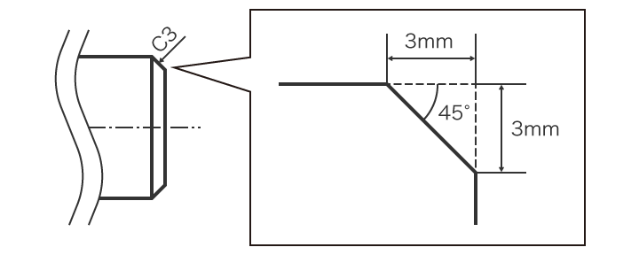
Chamfered surfaces are often indicated in drawings by a combination of the letter C and a number, for example C5 or C10. C naturally stands for “chamfering,” and usually indicates a surface chamfered at a 45-degree angle. The number next to C is the length (mm) of edge part to be cut off. In other words, this indicates a surface chamfered at a 45-degree angle to remove an area of the edge that forms an isosceles right triangle with the indicated length being the length of the two equal sides. The figure below shows the drawing notation and machining details for an example of C3.
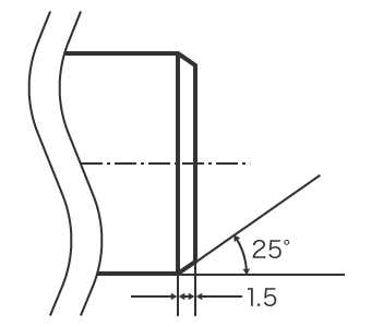
When the corner to be cut off does not have a 45-degree chamfered surface angle, the angle and the length of the side with that angle are indicated in the drawing. For example, when a corner 1.5 mm (0.06") on a side is cut off at 25-degree angle, the chamfering is indicated as shown below.
How to Calculate the Depth of a Chamfered Surface
When a corner is chamfered by putting the tool in contact with the target at a 45-degree angle, or the other way around, the depth which should be cut off can be determined by calculating the depth from the triangle sides.
The depth to be cut off is indicated by D. In the case of C1, the depth to be cut can be calculated with the following formula.
- D = 1.0 / √2 ≈ 0.7 (mm)
- To find D, divide the isosceles right triangle with sides of 1 mm (0.04") in half. D is the length of the short side of the new isosceles right triangle where the long side is 1.0.
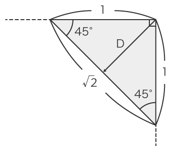
The ratios of the sides of an isosceles right triangle is 1:1:√2.
This ratio can be simplified as shown below.
- D ≈ 0.7 (mm)
- With this formula, it is easy to know the depth of a corner to be cut off at a 45-degree angle. For example in the case of C4, the depth is D x 4 ≈ 2.8.
Measurement Difficulties
It is extremely important to verify that chamfering has produced the intended dimensions (within tolerances) and shape. Chamfered surfaces are three dimensional, and require high-accuracy, quantitative 3D shape measurement.
However, because the shape three-dimensional, and typically small, obtaining accurate measurements can be difficult.
Measurement difficulties - CMM
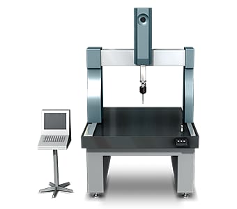
A coordinate measuring machine ordinarily contacts the target at three to six points with a probe, and then creates a virtual surface in order to measure the chamfered surface. This measurement method has the following problems:
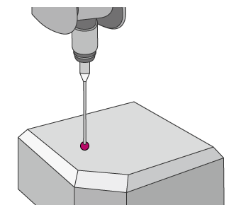
- When the chamfered surface to be measured is small, for example 1 mm2, it is extremely difficult to measure the shape accurately by pinpointing the surface with a probe and creating a virtual surface.
- Programming and operating CMMs can be difficult and time consuming, particularly when measuring small features. To measure chamfers, CAD drawings typically need to be used to program the machine, further increasing the knowledge required to perform measurements.
For this reason, one major problem with 3D measuring instruments is that not all workplace operators can measure chamfered surfaces accurately. In addition, the chamfered surface is measured based on the intersections of the created virtual surface, and cannot reflect the actual shape.
Measurement difficulties - Profilometer
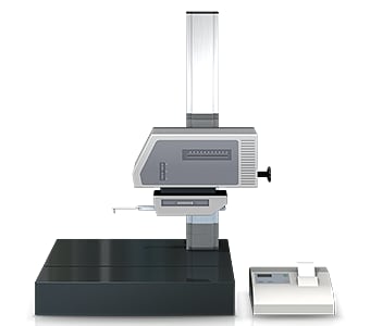
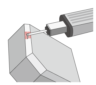
Profile measurement systems must acquire an accurate measurement line perpendicular to the shape of the chamfered surface to be measured. This involves the following problems:
- The part must be fixtured and leveled before measurement.
- Knowledge and skills regarding the use of a profile measurement system are also required in order to level a target accurately.
- Tracing the desired line with the stylus is extremely difficult work, and even slight displacement of the stylus produces error in the measured values.
Measurement difficulties - Hand tools
Handheld tools such as chamfered surface calipers or a gauge allow very convenient measurement. However there are multiple causes which result in measurement error or variation in the measurement data.
With calipers or a gauge, measurement conditions such as the contact force (measuring force) when measuring each point by hand and selection of the measured points differ depending on the operator. This results in variation in the measurement values and makes it difficult to obtain quantitative measurements.
Chamfered Surface Measurement Solutions
Reviewing the problems of conventional measuring instruments shows that there is a certain point which the problems all have in common. This is that measurement of a three-dimensional target or area is done by means of point and line contact.
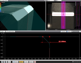
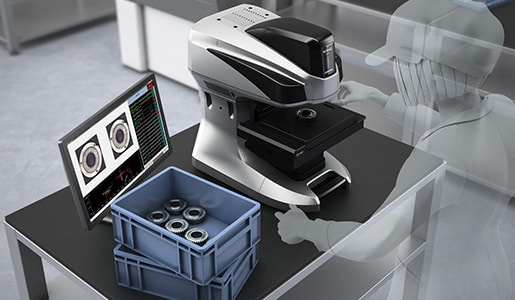
To resolve these measurement problems, KEYENCE has developed the 3D Optical Profilometer VR Series. The VR Series accurately captures the 3D shape of the entire target surface without contacting the target. A 3D scan of the target on the stage can be completed in as little as one second, for high accuracy measurement of the 3D shape.
Advantage 1: No measurement variation
The VR Series can automatically find edges, and draw profile lines perfectly perpendicular to the edge to capture accurate measurement data to eliminate variation in results.

The wide variety of assist tools make it easy to perform accurate measurement.
Once a target has been scanned, its profile (cross-section) can be measured at locations different from those which were measured in the past. This eliminates the need to set and measure the same target again. This also enables comparisons with past data to check the differences in shape when a workpiece is supposed to have the same shape but was manufactured in a different lot using different materials under different processing conditions.

Advantage 2: No fixturing required
Measurement can be performed simply by placing the target on the stage and pressing a button. Strict positioning or other preparation is not required.
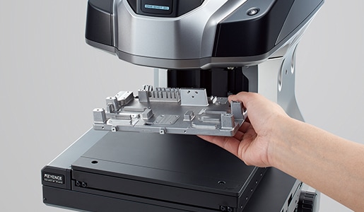
Unlike conventional measuring instruments, the VR Series extracts the features of the target placed on the stage and automatically corrects its position. The strict positioning which previously required much time and effort is no longer necessary. This makes it possible for even an inexperienced operator to easily and instantaneously perform measurement, and eliminates the need to assign a specialized operator to measurement work.
Advantage 3: Rapid, high-accuracy measurement
The entire surface can be scanned for measurement in as little as one second.
Because the VR Series is capable of measuring targets quickly and easily, it can be used in high-accuracy 3D measurement for a wide range of purposes. In addition to development and trials, it can also be used for sampling inspections or 100% inspections of small-lot or high-value products. It can reduce the outflow of defective products and allows reports to be created easily. This contributes to earning trust without having to invest an excessive amount of man-hours.
Summary: Dramatic Improvement and Higher Efficiency for Chamfer Measurements
The VR Series resolves the problems faced by conventional measuring instruments by instantaneously measuring accurate 3D target shapes with high-speed, non-contact scanning.
- Measurement variation between different operators is eliminated.
- Without the need for positioning or other preparation, measurement can be done simply by placing the target on the stage and pressing a button. This eliminates the need to assign a specialized operator for measurement work.
- 3D shapes can be measured easily at high speeds with high accuracy. This makes it possible to measure a large number of targets in a short time, helping to improve quality.
This system also allows comparisons with past 3D shape data and CAD data, as well as easy data analysis such as distribution within tolerances. It can be used effectively for a wide range of purposes including product development, manufacturing trend analysis, and sampling inspections.
