3D Measurement of Connectors
The recent popularization of digital equipment and communication devices have resulted in an increased demand for connectors.
Meanwhile, connector types and applications have also increased, leading to an even greater need for product inspection and analysis. KEYENCE’s latest model in the VK-X Series is capable of repeat measurements, automatic measurement of multiple locations of the same target, and creation of OK/NG analysis templates.
This section introduces technical information related to connectors as well as example inspections using 3D surface profilers.
- Connector Overview
- Connector Terminology
- Connector Structure
- Connector Purposes and Categories
- Connector Inspection Examples
Connector Overview
A connector is a device used for joining wiring for electronic circuits and optical communication. The use of connectors makes attachment/detachment and connection easier.
Merits of using a connector
- (1) Replacement with a new one makes repairs easy.
- (2) Easy to upgrade with modularization.
- (3) Parts can be easily assembled and productivity can be improved.
Connector Terminology

- A
- Device/panel
- B
- Receptacle
- C
- Plug
- D
- Cable
- E
- Jack
- Plug
-
The male side of a pair of mating connectors that has a needle shaped contact.
It is used in conjunction with a jack.
- Jack
-
The female side of a pair of mating connectors that has a lattice-shaped contact for the insertion.
- Receptacle
-
To be used with a plug but attaching it to a panel or box

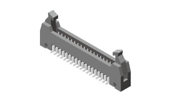
- Header
-
This connector is used to connect a flat cable. The male side is called the header and is used as a set with the socket.
- Socket
-
This connector is used to connect a flat cable. The female side is called a socket.
Connector Structure
Contact
Terminals that make electrical contact when the connectors are mated. Two common type include knife-fork contacts and bellows contacts.
- Knife fork contact
-
The name comes from the fact that the structure of the contact is similar to a knife and fork.

- Bellows contact
-
The name comes from the fact that the shape of the contact resembles a bellows. This contact is formed by bending a thing plate and is highly reliable due to surface contact.

Terminal
Terminals are used for connecting to a printed circuit board. Depending on the mounting direction needed, straight and right angle connectors can be used.


Housing
Housing is an insulator to hold the contact (can also be called the shell).
Connector Purposes and Categories
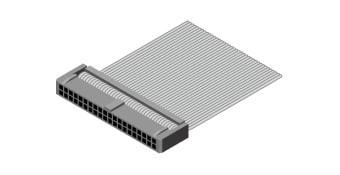
Connection within the device
- Connection with the PCB and line
-
Flat cable connections are mainly used inside of devices.
They consist of a set of header and socket.
- Board-to-board connection
-
The shape of the connector differs when boards are stacked on the top and bottom and when one side is connected standing up. It is used as the header and socket set.

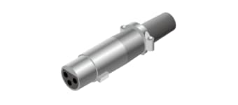
Device to device connection
When used between devices, they are also called I/O (input/output) connectors or I/F (interface) connectors. Circular, square, coaxial, and optical connectors are common.


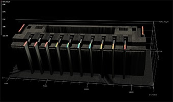
Connector Inspection Examples


The surface measurement function can also automatically measure the maximum and minimum surface points.


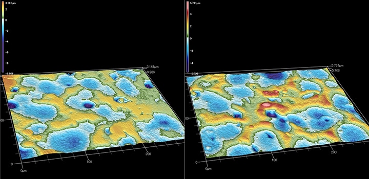
The collapsed apex shape at the periphery indicates strong reflection.
