Bolts and Screws Underhead Shape Measurement
Bolts and screws come in many types and are classified according to their length, thickness, shape, and purpose. There are products where these characteristics are standardized and also special products which are designed for a particular purpose. What is common to all bolts and screws is that they must be machined to high accuracy within the tolerances that are specified in the standards or design.
This section explains basic knowledge and functions of the part called the underhead, which requires the highest level of accuracy, as well as problems when measuring it and solutions to those problems.
- Underhead
- Screw Thread Structure
- Difference Between Full Threads and Half Threads
- Function of Round Underhead Shape
- Problems in Conventional Measurement of Round Underhead Shape
- Screw and Bolt Measurement Solutions
- Summary: Dramatic Improvement and Higher Efficiency for Shape Measurements of Bolts and Screws
Underhead
Surface area is an important indicator when evaluating functionality, together with texture, adhesion, sliding performance, heat dissipation, and roughness. Measuring the surface area can provide information on many crucial properties of screw performance.
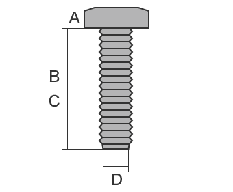
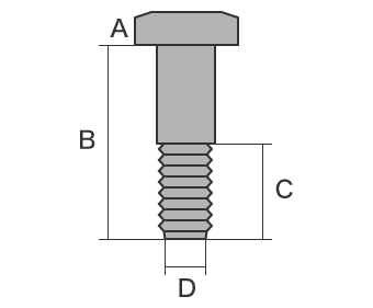
- A
- Head
- B
- Underhead
- C
- Thread length (underhead length)
- D
- Thread diameter
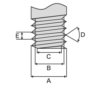
- A
- Outer diameter
- B
- Effective diameter
- C
- Core diameter
- D
- Screw thread angle
- E
- Pitch
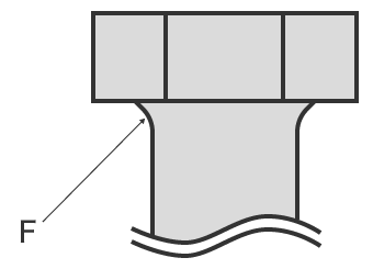
- F
- Round underhead shape
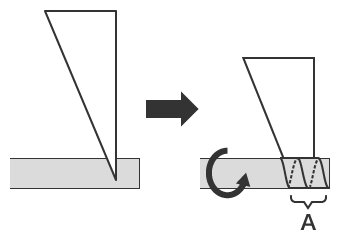
Screw Thread Structure
The thread is a line with a right triangular shape that wraps around the cylinder in a spiral. This line is called the helix, and various structures are used for the spiral-shaped crest and root to change the friction force, strength, or accuracy.
The distance which a bolt or screw advances in an axial direction when rotated one time is called the lead. In a single-thread screw, the lead is equal to the pitch. The angle formed by the length of a single rotation of the threads relative to the lead is the lead angle.
- A
- Helix
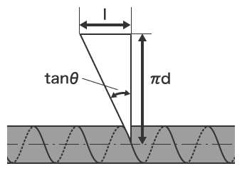
- tan θ
- Lead angle
- l
- Lead (mm)
- π d
- Length of one thread rotation (mm)
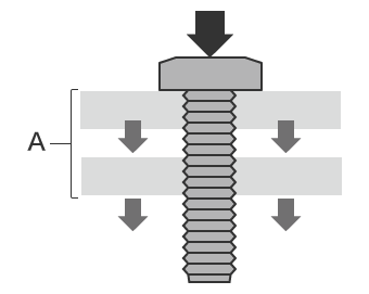
Difference Between Full Threads and Half Threads
The most important function of bolt and screw threads is fastening force (anchoring force produced by tightening the bolt or screw). They also produce the force that holds parts together. "Full threads" contain threads on the entire underhead, and "half threads" contain threads on only a limited area.
Because full threads have strong fastening force, they produce strong anchoring force. However, when there is a gap between two plates, it is impossible to fasten them together and eliminate the gap. On the other hand, half threads can apply fastening force to either one plate or the other, and they are used for fastening two parts together without a gap between them.
Example: Fastening two plates together
When a full threaded bolt or screw is fully tightened, the gap still remains.
With half threads, screw fastening force is applied to one plate only, pulling it toward the other plate and eliminating the gap.
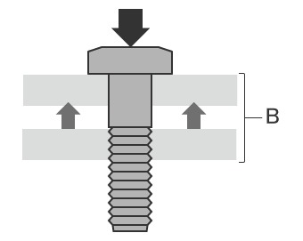
- Fastening force
- Force applied to plate
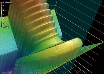
Function of Round Underhead Shape
Because of the sudden change in cross-section at the head and underhead part, stress concentration occurs and may cause the head to break off as a result of fatigue fracture. To avoid this, machining to produce a round underhead shape is performed. Fatigue strength can be further improved by forming a rounded corner and by eliminating any unevenness on the surface. Recent studies have shown that a combination of a rounded shape and tapered edge is most effective as a countermeasure to stress concentration.
A round underhead is used for aircraft engine bolts where high-precision machining by rolling compaction is required, and where particularly high strength is needed.
Problems in Conventional Measurement of Round Underhead Shape
Bolt and screw quality has improved as a result of advances in production engineering, however it is difficult to completely prevent the occurrence of defects. When there is a problem such as burrs, cracking, chipping, deformation, dimensional deviation, or forming defect of the round underhead, not only is the part unable to fulfill its function as a fastening part, but the product where the bolt or screw is used may be damaged. Here we will introduce common defects which occur in the screw and bolt manufacturing process, and the causes of their occurrence.
Measurement Difficulties - Optical Comparator
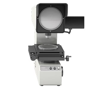
An optical comparator is a type of optical measuring instrument, and the measurement principle is similar to that of an optical microscope. This measuring instrument emits light from below a target which is placed on the stage, projecting the target profile onto a screen. Some large optical comparators have screen diameters that are larger than 1 m (3.3′). When measuring a round underhead, it is necessary to accurately position the target bolt or screw.
- As the shape is 3-dimensional, it is difficult to focus the light on the entire surface of the underhead part. It is also difficult to define the range of underhead roundness in the 2D projection image and variation in the measurement value may occur with different operators. Furthermore, differences between the projected dimensions and the drawing cannot be obtained in numerical form, and the profile shape must be transferred to tracing paper, making it difficult to store and compare the data.
- Because an optical comparator obtains a cross-section observed only from the direction perpendicular to the cut surface, the target bolt or screw must be positioned so that the round part under the head can be seen, and must be accurately leveled for measurement. However, the fact that there is inconsistency in how the target is placed is a problem.
The problems outlined above make it difficult to obtain accurate and repeatable measurement results.
Measurement Difficulties - Profilometer
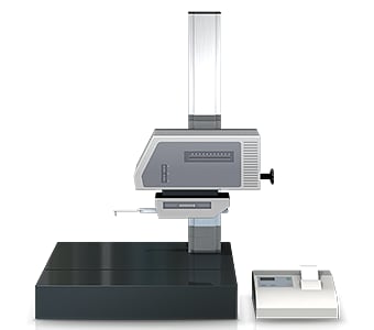
A profilometer measures and records the profile of a target by tracing its surface with a stylus. In recent years, profile measurement systems have been developed that use a laser instead of a stylus to measure complex shapes by tracing the profile in a non-contact manner. Some models are even able to perform measurement of both the top and bottom surfaces.
When a profile measurement system measures a bolt or screw, the part must be positioned so it is level.
It is common to encounter the following problems when measuring with a profilometer:
- Measurement is time consuming, including the time require to fixture the target and level it.
- The stylus of a profile measurement system moves up and down in an arc centered on the fulcrum of the stylus arm, and the tip of the stylus also moves in the X-axis direction. This produces error in the X-axis data.
- Tracing the desired line with the stylus is extremely difficult work, and even slight displacement of the stylus produces error in the measured values.
Screw and Bolt Measurement Solutions
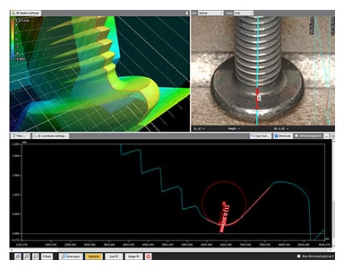
The measuring instruments that are typically used are time consuming, and require subjective decisions to be made during fixturing and evaluation that affects the measurement data. To resolve these measurement problems, KEYENCE has developed the 3D Optical Profilometer VR Series.
The VR Series accurately captures the 3D shape of the entire target surface without contacting the object. The VR Series does not require special fixturing or subjective decisions to be made, enabling accurate measurements to be performed by any operator.
Advantage 1: Captures data across the entire surface
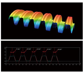
KEYENCE has fully reviewed the measurement algorithms and hardware, enabling the entire surface to be scanned in just one second. Measurement can automatically be performed on the desired target points, such as the round underhead shape and thread pitch.
With impressive measurement speeds as fast as one second, the VR Series makes it possible to substantially increase the number of samples that are measured, and to shorten the work time. This leads to improvements in measurement quality, allows inspection operators to be reassigned as production operators, and helps boost production quantities. This also improves the speed of all measurement tasks such as prototype evaluations and shipping inspections.

Advantage 2: No variation between operators
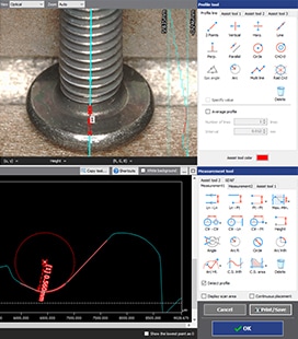
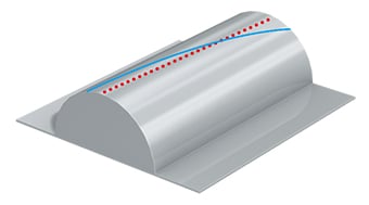
The VR Series can automatically extract the cylindrical shape of the screw or bolt and ensure that the profile measurement line is drawn directly in the center. This eliminates variation in the measurement results and ensures different operators will obtain the same measurement results.
Once a workpiece has been scanned, its profile (cross-section) can also be measured at locations different from the locations used in past measurement. This eliminates the need to set and measure the same target again. This also enables comparisons with past data to check the differences in shape when a workpiece is supposed to have the same shape but was manufactured in a different lot using different materials under different processing conditions.
Advantage 3: Automatic scanning and measurement
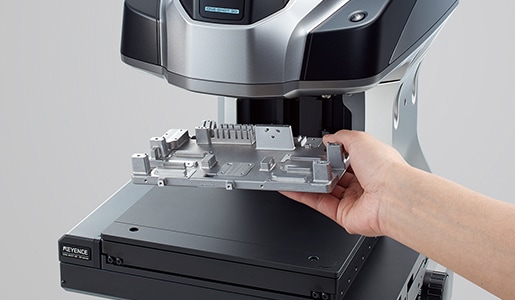
The VR Series includes a Smart Measurement function which automatically recognizes the width and height of the target in order to automatically set the optimal measurement range. Eliminating the need to set measurement lengths, Z ranges, and other aspects required with general measuring instruments, the VR Series prevents mistakes such as failing to measure a certain part of the target.
Tilt and misalignment can be automatically corrected with the system, so no precise fixturing is required.
Summary: Dramatic Improvement and Higher Efficiency for Shape Measurements of Bolts and Screws
The VR Series can measure 3D target shapes accurately and instantaneously by high-speed 3D scanning without contacting the target. Difficult measurements such as outer diameter, effective diameter, core diameter, thread angle, pitch, and round underhead shapes can be completed in as little as one second. The VR Series solves all the problems experienced with conventional measuring instruments.
- Because measurement is non-contact, this enables measurement of cross-sections where a stylus cannot reach. Even round underhead shapes and thread pitch can be measured easily and accurately.
- Built-in assist tools eliminate measurement variations between different operators.
- Without the need for positioning or other preparation, measurement can be done simply by placing the target on the stage and pressing a button. This eliminates the need to assign a specialized operator for measurement work.
- 3D shapes can be measured easily at high speeds with high accuracy. This makes it possible to measure a large number of targets in a short time, helping to improve quality.
This system also allows comparisons with past 3D shape data and CAD data, as well as easy data analysis such as distribution within tolerances. It can be used effectively for a wide range of purposes including product development, manufacturing trend analysis, and sampling inspections.
