Accurately Measure Shear Droop on Cut Surfaces
There are many types of press machining including shearing, bending, and drawing. Among these types, shearing also includes piercing and notch machining. The surface produced by shearing is the cut surface, and by inspecting the shape of the cut surface, it is possible to identify conditions such as the clearance between the punch and die.
This section explains basic knowledge of shearing and the principle of droop occurrence. It also introduces problems in measurement of droop and other shearing cross-sections, and a solution to those problems.
- Shear Droop
- Cut Surface Resulting From Shearing
- Clearance
- Shearing Process
- Droop Measurement Difficulties
- Droop Measurement Solutions
- Summary: Dramatic Improvement and Higher Efficiency for Droop Measurement
Shear Droop
Shear droop is a phenomenon that occurs on the surface of a product that was machined by shearing. When the machined material is cut using a punch and die, the material is pulled by the tensile force produced on the cut surface, producing a smooth surface. This smooth surface is known as droop. The size and shape vary depending on the clearance between the punch and die. Clearance between the punch and die has a large effect on product quality, as well as the service life of the press machine.
Cut Surface Resulting From Shearing
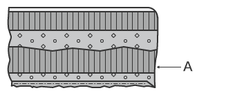
The cut surface that results from shearing is composed of four layers: droop, shear surface, fracture surface, and burrs. Even when the workpiece is a flat sheet, the surface is not smooth.
As explained above, droop is a smooth surface that was created as a result of tension at the surface of the machined material. The shear surface is a glossy surface that is created by the punch which was inserted into the machined material. There are fine vertical stripes on the shear surface that were formed as a result of abrasion by scratches on the punch, deposited metal, or other substance. The fracture surface is rougher than the shear surface, looking like the machined material was ripped away. The burrs have hard, sharp shapes and jagged edges.
The conditions of the cut surface vary depending on the machined material, punch lowering speed, and the size of the clearance between the punch and die.
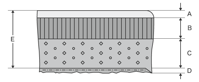
- A
- Droop
- B
- Shear surface
- C
- Fracture surface
- D
- Burrs
- E
- Sheet thickness
Clearance
Clearance refers to the gap between the punch and die. The conditions of the cut surface vary depending on the size of the clearance. When clearance is set correctly, it is referred to as optimum clearance.
The size of the clearance is very important because it affects the shear quality (such as dimensional accuracy and prevention of droop/burrs), as well as the service life of the die. When optimum clearance is set, the cracks starting from the punch side and the die side meet in the middle. With ideal shearing, there would be a full shear surface with no droop or burrs. However, this is difficult to achieve even with optimal clearance.
The relationship between the set clearance and the cut surface is shown below.
Optimal clearance
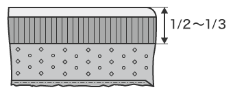
When optimal clearance is set, the shear surface is even and covers 1/2 to 1/3 of the sheet thickness. When clearance is not constant, the shear surface ratio will vary at different parts.
Too large clearance
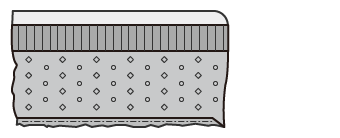
When clearance is too large, droop and burrs become larger and product accuracy becomes unstable. Warpage (blanking warpage) caused by the blanking pressure also becomes larger.
Too small clearance
- A
- Secondary shearing
When clearance is too small, the fractures initiated from the cutting edges of the punch and die do not match (meet), and fibrous burrs occur as a result of the secondary shearing surface. The load on the punch and die is also large and can cause mold damage called galling.
The optimal clearance value differs depending on the machined material and sheet thickness. A general purpose value can be calculated using the following formula.
Single side clearance = % x Machined sheet thickness
* [%] indicates the ratio of clearance to sheet thickness. Because this may differ depending on the material or blanking accuracy, calculate from the actual test value.
Shearing Process
The process of cutting by shearing is as shown below.
(1) The punch presses on the top of the machined material.
- The sheet bends, and droop occurs in the machined material.
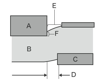
- A
- Punch
- B
- Sheet metal
- C
- Die
- D
- Clearance
- E
- Droop
- F
- Shear surface
(2) When the material cannot bend further, the punch sinks into the material.
- As a result of shear force produced by the punch and die, cracking occurs.
- When the machined material cannot withstand the tensile force, cracking of the machined material occurs.
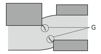
- G
- Cracks
(3) Tensile force is applied to machined material by the corners of the punch and die.
- When the cracks from the punch and die blade grow until they pass all the way through, burrs are produced.
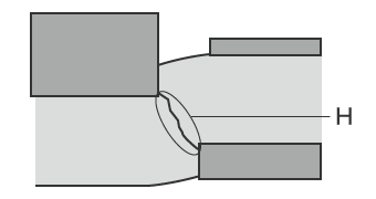
- H
- Through-crack
Shearing is the process that produces the shear surface while shearing force is acting on machined material.
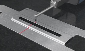
Droop Measurement Difficulties
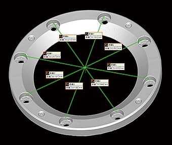
In most conventional cases of measuring press droop, an optical comparator or profilometer is used. However, performing pinpoint measurement of droop in a large sheet material can be difficult.
Measurement difficulties - Optical comparator
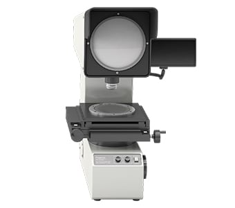
An optical comparator is a type of optical measuring instrument, and the measurement principle is similar to that of an optical microscope. This measuring instrument emits light from below a target which is placed on the stage, projecting the target profile onto a screen. Some large optical comparators have screen diameters that are larger than 1 m (3.3′). When measuring droop on a large surface after punching, the part must be positioned so it is level.
This measurement method can experience the following problems:
- Because the optical comparator obtains a cross-section observed only from the direction perpendicular to the cut surface, the target must be placed so that the droop part can be seen, and must be accurately leveled for measurement. However, inconsistencies in how the target is placed can cause measurement variations.
- When the workpiece shape is complex, there may be parts which are in optical shadow and cannot be measured from the perpendicular direction. Furthermore, differences between the projected dimensions and the drawing cannot be obtained in numerical form, and the profile shape must be transferred to tracing paper, making it difficult to store and compare the data.
This results in a number of measurement problems, including some locations which cannot be measured and require the target to be cut.
Measurement difficulties - Profilometer
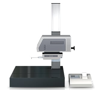
A profile measurement system measures and records the profile of a target by tracing its surface with a stylus. In recent years, profile measurement systems have been developed that use a laser instead of a stylus to measure complex shapes by tracing the profile in a non-contact manner. Some models are even able to perform measurement of both the top and bottom surfaces.
When using a profile measurement system to measure droop on a large surface after punching, the part must be positioned so it is level.
This measurement method experiences the following problems:
- The target must be fixtured and leveled before measuring.
- The stylus of a profile measurement system moves up and down in an arc centered on the fulcrum of the stylus arm, and the tip of the stylus also moves in the X-axis direction. This produces error in the X-axis data.
- Tracing the desired line with the stylus is extremely difficult work, and even slight displacement of the stylus produces error in the measured values.
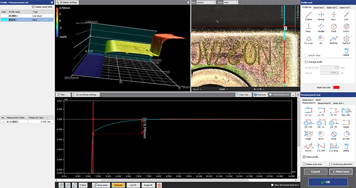
Droop Measurement Solutions
The measuring instruments that are ordinarily used involve issues such as the long time required to position the target, and the fact that measurement of three-dimensional targets and areas is performed by means of point or line contact. To resolve these measurement problems, KEYENCE has developed the 3D Optical Profilometer VR Series.
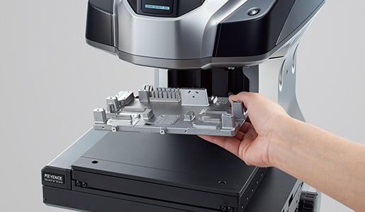
The VR Series accurately captures the 3D shape of the entire target surface without contacting the object. The VR Series does not require special fixturing or subjective decisions to be made, enabling accurate measurements to be performed by any operator.
Advantage 1: No fixturing required.
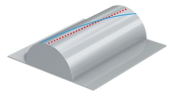
The VR Series is capable of measuring droop without adjusting or fixturing the target.
The VR Series can perform accurate measurement of droop by measuring the entire surface by non-contact means. Workpiece shapes can be analyzed in a short time by using the analysis templates which allow users to register the measurement items in advance. This makes it possible to rapidly perform measurement which previously required a lot of time.

Advantage 2: The automatic positioning function eliminates complex settings.
The VR Series automatically sets the measurement range and scan settings, requiring the user to just place the target on the stage. No time-consuming adjustments are required, allowing any user to capture accurate data within seconds.
Advantage 3: Capture the entire surface shape in as little as one second.
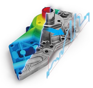
KEYENCE has fully reviewed the measurement algorithms and hardware, enabling the entire surface to be scanned in just one second. Measurement can automatically be performed on the desired target points with no measurement variation between users.
This leads to improvements in measurement quality, allows inspection operators to be reassigned as production operators, and helps boost production quantities. This also improves the speed of all measurement tasks such as prototype evaluations and shipping inspections.
Summary: Dramatic Improvement and Higher Efficiency for Droop Measurement
The VR Series can measure 3D target shapes accurately and instantaneously by high-speed 3D scanning without contacting the target. It solves all the problems involved with conventional measuring instruments including measurement of the boundaries between the droop, shear surface, fracture surface, and burrs.
- No cutting or destructive testing.
- No measurement variation between different operators.
- Without the need for positioning or other preparation, measurement can be done simply by placing the target on the stage and pressing a button. This eliminates the need to assign a specialized operator for measurement work.
- 3D shapes can be measured easily at high speeds with high accuracy. This makes it possible to measure a large number of targets in a short time, helping to improve quality.
This system also allows comparisons with past 3D shape data and CAD data, as well as easy data analysis such as distribution within tolerances. It can be used effectively for a wide range of purposes including product development, manufacturing trend analysis, and sampling inspections.
