Measuring Sink Marks
Sink marks occur when the surface of a molded product shrinks and forms slight depressions or craters. Although sink marks do not affect part strength or function, they are considered a quality defect. There are also cases in which a cavity occurs on the inside of the product. This is called a void. Both sink marks and voids occur as a result of abnormal shrinking during the process of cooling and solidifying the molten plastic material.
This page introduces ways to reduce and measure sink marks using a 3D optical profiler.
- Sink Marks
- Countermeasures to Sink Marks in Mold Design
- Measuring Sink Marks
- Solution to Problems in Sink Mark Measurement
- Summary
Sink Marks
Sink marks mainly form during the cooling process when areas of hot liquid resin cool and shrink at different rates. Sinks are most common in thicker sections of molded parts as these thicker sections contain more plastic, taking longer to cool. Although it depends on the circumstances, sink marks can be prevented when there is no large difference in the cooling conditions between the inside and outside of the product. Below are 5 ways you can prevent sink marks from happening.
- Lower the temperature of the plastic material.
- Lower the temperature of the mold (or raise the temperature depending on the circumstances).
- Reduce the differences in product wall thickness (use undercuts to make the product thinner).
- Increase the injection pressure.
- Increase the holding pressure and holding time.
Be aware that when surface rigidity is strong comparing with the shrinking force, voids may be generated at the center inside the product.
Countermeasures to Sink Marks in Mold Design
The section below introduces three countermeasures to sink marks that can be applied at the mold design stage.
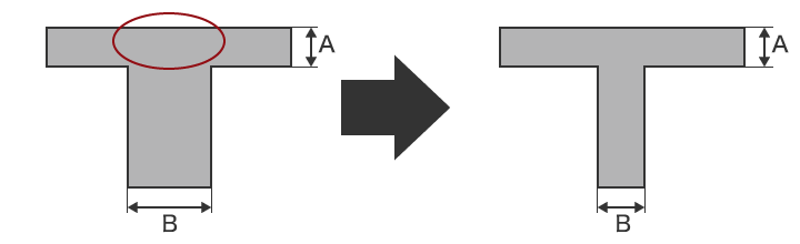
Reduce wall thickness
In general, the thicker parts cool more slowly than the thinner parts. Sink marks are more likely to occur at such parts (shown by the red circle in the figure below). In this case, it is possible to eliminate the sink mark by changing the wall thickness of the plastic molded product. For example, changing thickness B in the figure so it is the same as A (or so it is 70% or less) can prevent the occurrence of sink marks.
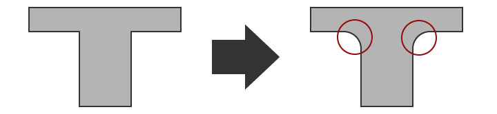
Changing shape to gradually decrease wall thickness
As previously stated, sink marks can be prevented by reducing thickness. However, there are some cases when the thickness cannot be changed. For example, sometimes thickness cannot be changed in order to maintain strength. In cases like this, you would want to change the shape so that wall thickness changes gradually. Looking at the example below, you can see how you can add rounded corners to resulting in a slight decrease in wall thickness.
In addition to shape changes, you could also add a cooling pipe at parts where heat accumulates or use materials that have high thermal conductivity.
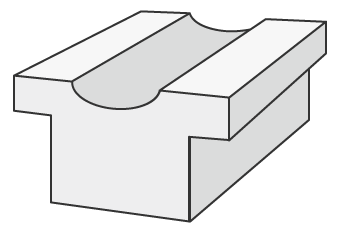
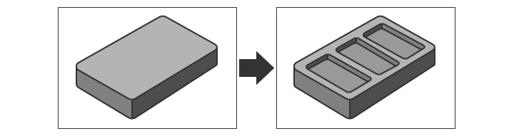
Adding undercuts and ribs
Adding undercuts or ribs can help reduce sink mark appearance when dealing with complex parts that require different levels of thickness. Adding undercuts and cross-sections of thicker parts in thicker areas can help reduce temperature allowing for a more even cooling process. Additionally, adding a cross-hatch rib pattern inside the undercut makes it possible to prevent sink marks while still maintaining strength. Gradually changing the wall thickness and chamfering are also effective in reducing sudden pressure changes in the mold.
Measuring Sink Marks
Not only are sink marks considered a cosmetic defect, but they can also be harmful to the structural integrity of the plastic part making it unusable. It is important to use the proper measurement tool to identify defect causes such as molding pressure, volume of injected material, and temperature. Conventional measurement tools including height gauges or coordinate measuring machines (CMMs) are sometimes hard to use resulting in inaccurate measurement. Below, we will discuss some of the issues found in conventional systems and introduce a new measurement technology that can offset some of these issues.
Problems in measurement using a height gauge
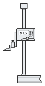
A height gauge can be used in combination with a dial gauge to measure height. Because measurement is limited to points, the whole shape cannot be identified making it impossible to obtain a complete view of the overall conditions. In addition, when measuring a flexible part, the measurement pressure may bend the part producing inaccurate measurements. Variation in measurement results between different operators and error in the measuring instrument itself also make stable and accurate measurement impossible.
Problems in measurement using a coordinate measuring machine
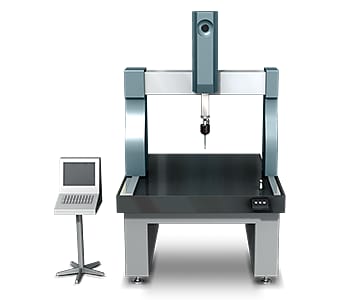
When measuring a small sink mark of 1 mm2, it is extremely difficult to measure the shape accurately by targeting that location with the probe and creating a virtual surface. It is also difficult to identify the accurate shape when measuring the 3D shape of a small area due to the small number of measurement points. Much work is also involved with related tasks such as tabulating the measurement data and comparing the results with the drawings.
Solution to Problems in Sink Mark Measurement
The measuring instruments that are ordinarily used involve issues such as the fact that measurement of three-dimensional targets and areas is performed by means of point or line contact, and the low reliability of the measurement values. To resolve these measurement problems, KEYENCE has developed the VR Series 3D Optical Profilometer.
The VR Series accurately captures the 3D shape of the entire target surface without contacting the target. It also measures the 3D shape by 3D-scanning the target on the stage in as little as one second with high accuracy. It is capable of instantaneous and quantitative measurement with no errors in the measurement results. This section introduces some specific advantages of the VR Series.
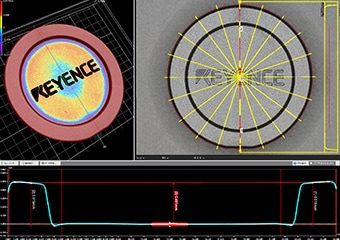
Advantage 1: Collect data from 800,000 measurement points.
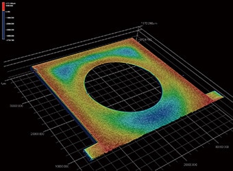
The VR-Series can also measure a wide area of up to 300 mm × 150 mm (11.81" × 5.91") while capturing up to 800,000 data points per scan. Because the entire shape can be identified and the high and low parts can be measured, it is possible to identify even slight sink marks as easily as large ones. All measurement data is stored, and the stored data can be compared with other data or with 3D design data.
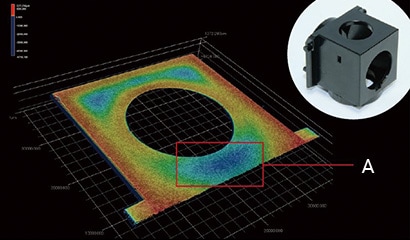
- A
- The blue area indicates a concavity.
Unlike conventional measuring instruments, the VR Series is capable of easily measuring sink marks that are scattered over a wide area. This type of measurement previously required much time and effort when using conventional systems. Measurement tools that allow a variety of measurements to be easily performed are also included. This makes it possible for even novice users to take accurate measurement, eliminating the need to assign a specialized operator to measurement work.

Advantage 2: Excel data output and CAD output are possible.
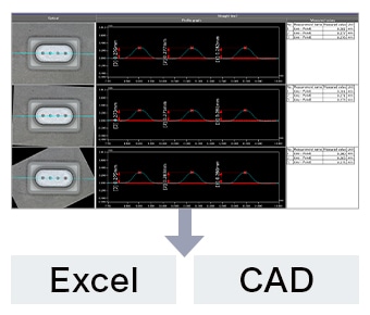
Data can be output to Excel exactly as it appears on the screen. Features such as the ability to sort each measured value, or to set a pivot table for summarizing data, make it possible to smoothly perform detailed examinations. In addition to STEP and ASCII, CAD data output in STL format is also supported. The created data can be utilized in a wide range of ways.
Summary
The VR Series can measure 3D target shapes accurately and instantaneously by high-speed 3D scanning without contacting the target. Even difficult measurement such as height and roughness of sink marks can be completed in as little as one second. The VR Series solves all the problems involved with conventional measuring instruments.
- Because it measures the entire surface, the VR Series can easily measure sink marks over a wide area. The highest points and lowest points can also be measured.
- This eliminates variation resulting from human factors, making true quantitative measurement possible.
- Without the need for positioning or other preparation, measurement can be done simply by placing the target on the stage and pressing a button. This eliminates the need to assign a specialized operator for measurement work.
- 3D shapes can be measured easily at high speeds with high accuracy. This makes it possible to measure a large number of targets in a short time, helping to improve quality.
This system also allows comparisons with past 3D shape data and CAD data, as well as easy data analysis such as distribution within tolerances. It can be used effectively for a wide range of purposes including product development, manufacturing trend analysis, and sampling inspections.
