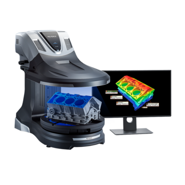
3D Scanner

Pressing is a type of plastic working; in some plastic pressing cases the shape may not be formed as designed. This is usually caused when stress remains inside the material after pressing due to factors such as springback. Caution is required when forming sheet material into a crank shape or U-shape by bending because corner parts may not form the prescribed angles and parallelism may deviate from the designated tolerances. In automobile frame manufacturing, the standard for tensile strength of steel sheet has been raised in recent years, and this makes high-precision pressing difficult.
This section explains problems with parallelism in pressing explaining knowledge about parallelism measurement, problems in parallelism measurement, and a solution to these problems.
Cause of Parallelism Error: Springback
The parallelism of the press machine bolster and slide surface as well as parallelism of the formed product is extremely important in pressing. When parallelism of the bolster and slide surface is not correct, the bend angle and drawing blank holder will be affected even when the slide moves vertically. This reduces the service life of the die. Parallelism failures of formed products after pressing occur primarily as a result of residual stress (internal stress) that exists inside of the formed product. This deformation is called springback, and it is a reason why maintaining the required dimensional accuracy during pressing is difficult.
Types of springback
Causes of spring back can be identified by investigating the conditions of internal stress inside the formed product at the press bottom dead center position. At bottom dead center during bending, tensile stress occurs on the outside of the bend and compression stress occurs on the inside of the bend. Die separation is caused when there are stress differences in the sheet thickness direction, ultimately changing the angle. Typical types of springback include angle change or warpage of the vertical wall at the rounded part of the die shoulder, twisting, and warpage of the ridge line. The stress which causes springback and examples of springback defects are explained below.
Angle change

A : Bending ridge line B : Angle change
This is a defect in which the angle of bend changes due to stress differences in the sheet thickness direction.
Wall warpage

A : Wall warpage
This is a defect in which the wall becomes warped due to stress differences in the length direction.
Twisting

A : Twisting
This is a defect in which the entire part becomes twisted due to the stress differences in the sheet thickness direction and to the stress acting towards the inside of the surface.
Warpage of the ridge line

A : Warpage of the ridge line
This is a defect in which the bending ridge line becomes warped due to the stress differences in the sheet thickness direction.
Countermeasures to parallelism springback
Countermeasures to spring back generally involve changing the die design or shape in the direction opposite to the direction where spring back occurs. By adjusting the amount of spring back and spring back direction into the press die, it is possible to achieve the dimensional tolerances.
Previously, countermeasures to spring back depended greatly on the designer’s intuition and experience, and modification of the die was performed after testing. However, because spring back tends to increase in proportion to the tensile strength of the steel sheet, a large number of die modifications may become necessary in cases when there is large spring back. To address this problem, simulations using FEM (Finite Element Method) are recently used in die design.
There are also other countermeasures such as “two-step bending” which performs bending twice with a single stroke of the machine. Additionally, “striking” adds projections to both corners of the punch cutting edge and “groove machining” creates a V-shaped indentation (V-notch) in advance at the part of the machined material which bends.
These countermeasures can be employed in cases when the cause of springback is known. Because the shapes of actual press formed products are complicated, it can be very difficult to identify the cause of springback. For this reason, a more effective method of calculating spring back is needed.
Calculating the amount of springback
If even a rough calculation of the amount of springback can be made, then it will be possible to enact countermeasures prior to machining. However, the calculation formula for predicting the amount of spring back is complicated, and in general it is used at the time of die design. For reference, the formula is shown below.
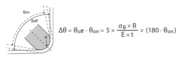
Δθ : Angle change resulting from springback
θon : Bending angle (°) when pressure is applied
θoff : Bending angle (°) after springback
σB : Steel sheet strength (N/mm2)
R : Punch curvature radius (mm)
E : Steel sheet Young's modulus (= 206,000 N/mm2)
t : Steel sheet thickness (mm)
* σB (steel sheet strength) and E (steel sheet Young's modulus) are inherent value of the material.
The cutting edge for bending is created based on the estimated amount of springback. It is difficult to calculate the error resulting from springback any further. In other words, it is easier to adjust the inner radius than to calculate the amount of springback. In addition, there is large error between the calculated value and actual value due to the effects of factors such as variation in sheet thickness and differences in machine specifications. This is why it is necessary to confirm the dimensional tolerance by measuring after forming.
Problems in Conventional Parallelism Measurement
Parallelism is a value that indicates how parallel each plane or line of a formed product is with regards to the perfect virtual plane or line that is the reference. It is measured by setting a virtual plane or line, and cannot be measured using a hand-held tool such as calipers or a micrometer. For this reason, parallelism of a pressed product is measured using a coordinate measuring machine or CNC image measuring instrument. However, parallelism measurement using these instruments requires precise and advanced technical skills and experience, and involves the following measurement problems.

Problems in parallelism measurement using a coordinate measuring machine
In general, when measuring warpage using a coordinate measuring machine, it is necessary for the probe to contact four or more corners on the measured surface of the target.
For example, when measuring a plate, generally six to eight points are measured. When the measurement area is large, measurement accuracy can be improved by increasing the number of measured points to collect more measurement data.
However, the following problems occur when a coordinate measuring machine is used for parallelism measurement.
- Because it is necessary to measure by contacting individual points, it is fundamentally difficult to identify the entire shape.
- Because measuring more points to acquire more measurement data requires much time, it is not possible to identify the detailed shape of the entire target.

Problems in parallelism measurement using a CNC image measuring instrument
In general, an image measuring instrument captures the target on the stage using a CCD camera and performs 3D measurement. Observation using color images is possible but there are the following problems when used for parallelism measurement.
- False detection may occur when there are protrusions on the target. In addition, when the measurement points or other settings are different, variation in measurement accuracy will occur.
- When the number of X, Y, Z, or other measurement items increases, the program becomes complex, requiring both advanced expert knowledge and man-hours for configuration. The required measurement man-hours increase in proportion to the number of measurement targets. There are major problems including the need for a measurement chamber, the need to keep the measurement chamber at the reference temperature, and the fact that accurate measurement cannot be performed by all workplace operators.
Solution to Problems in Parallelism Measurement
The coordinate measuring machines that are ordinarily used require much time to perform measurement because they measure three-dimensional targets and measurement locations by performing contact measurement of multiple points. Additionally, problems such as low measurement value reliability due to variations caused by human factors and difficulty creating usable data from the numbers, analysis functions and other post-processing techniques can be seen with this type of tool.
To resolve these measurement problems, KEYENCE has developed the VR-Series 3D Optical Profilometer and the VL- Series 3D Scanner CMM.
These products accurately capture the 3D shape of the entire target surface without contacting the target. They also measure the 3D shape by 3D-scanning the target on the stage in as little as one second with high accuracy. This section introduces some specific advantages of these systems.

VR Series Advantage 1: Up to 800,000 points can be measured within a single scan, eliminating the need to repeat measurement.
The VR-6000 can capture up to 8000,000 data points across an entire surface (12" X 6" area) in as little as one second. Since measurement is not performed using lines or points, no repeat measurement is required, reducing overall time spent taking measurements. Measurement which requires datum such as parallelism or perpendicularity is also easy. Measurement data is automatically stored, and the stored data can be compared with other data or with 3D design data.
Unlike a coordinate measuring machine or CNC image measuring instrument, the VR-Series extracts the features of the target placed on the stage, and automatically performs position correction. The strict positioning which previously required much time and effort is no longer necessary. This makes it possible for any type of operator, regardless of experience level, to easily and instantaneously perform measurement.
With the VR-Series, even parallelism of targets with complex shapes can be accurately measured simply by placing the target on the stage and pressing a button.

VR Series Advantage 2: Quantitative comparison and analysis of multiple sets of measurement data are possible.
The VR Series can measure the 3D shape of the entire target by 3D-scanning the target surface in as little as one second. This makes possible to measure a large number of targets with no sample prep required. Measurement locations or number of measurement points does not need to be set up as the system will automatically set the measurement conditions for you.
Multiple sets of measurement data can be displayed in a list and the same analysis contents can be applied to all data sets at the same time.
Differences in the shape data of multiple targets can be confirmed at a glance. This makes it possible to perform batch analysis of parallelism in multiple data sets, and easily perform quantitative evaluation of how much an NG part is warped compared to an OK part.

Spherical center

Axis of cylinder

Midpoint

Intersection

Max. height

Min. height

Center line

Vertical baseline
A wide variety of assist tools allows simple setup of the desired measurement contents.
In addition to easy configuration, the assist tools allow even novice users to take shape measurements quickly and accurately. As a result, the number of samples can easily be increased not only for prototypes and trials, but also for measurement and inspection of products.

VL Series Advantage 1: Performs non-destructive 360° scanning of the entire object.
The VL Series 3D Scanner CMM can scan 360° around an entire object.
While conventional wall thickness measurement method require users to cut their product, the VL enables cross-section shape measurement without any cutting. The VL Series enables anyone to easily perform non-destructive measurement of the cross-sectional shape and easily manage the wall thickness.
The scanned data can be compared with CAD data to easily identify the optimal dimensions and resolve problems caused by springback. Accurate 3D data can be acquired through non-contact means for workpieces that have curved surfaces as well. Because data for several million points can be acquired without contacting the workpiece making it possible to identify the overall shape even on complex shapes.
VL Series Advantage 2: Accurate measurement is possible without using a jig or fixing the target in place.
When a pressed product is forcibly fixed in place using a jig, deformation occurs and the actual shape cannot be measured correctly.
With the VL Series, non-contact scanned data of the entire target can be compared with CAD data to easily identify the optimal die dimensions and resolve problems caused by springback.

With a curved surface shape, it is difficult to identify the entire shape with a contact-type measuring instrument even when multiple points are measured.
Because the VL Series acquires non-contact shape data for several millions points, it is possible to accurately identify the entire workpiece shape—something that was difficult to measure before.
Summary: Comprehensive Improvement and Higher Efficiency for Problems in Parallelism Measurement of Press Formed Products
The VR Series and the VL Series can measure 3D target shapes accurately and instantaneously using high-speed 3D scanning without contacting the target. Parallelism measurement can be completed instantaneously for small parts, large parts, and parts with complex shapes. These products can solve all the problems involved with conventional measuring instruments.
- Because the entire surface data can be captured by non-contact means, it is possible to measure cross-sections where a stylus cannot reach. Parallelism can be easily and accurately measured even for small parts.
- A wide variety of assist tools resolve the problem of variation in measurement values caused by human factors. This makes it possible to perform true quantitative measurement.
- Without the need for positioning or other preparation, measurement can be done simply by placing the target on the stage and pressing a button. This eliminates the need to assign a specialized operator for measurement work.
- 3D shapes can be measured easily at high speeds with high accuracy. This makes it possible to measure a large number of targets in a short time, helping to improve quality.
This system also allows comparisons with past 3D shape data and CAD data, as well as easy data analysis such as distribution within tolerances. It can be used effectively for a wide range of purposes including product development, manufacturing trend analysis, and sampling inspections.