Easy and Accurate Measurement of Tapers
Taper is a term used to describe the narrowing of an object or surface. This page introduces the basics of tapers, including their purpose, types of parts that utilize them, methods for calculating them, how they are produced, and common problems and solutions associated with measuring them.
- Tapers
- Parts Where Tapers Are Used
- Calculating Taper Angle
- Taper Production Methods
- Problems in Conventional Taper Measurement
- Solution to Problems in Taper Measurement
- Summary: Dramatic Improvement and Higher Efficiency in Measurement of Tapers
Tapers
Taper indicates conditions in which the diameter, width, or thickness of a long, narrow structure gradually becomes smaller toward the tip. There are many different types of taper shapes, which are selected according to the purpose of use. Tapers are used to strengthen a structure or make fitting easier, and are formed by processes such as pressing or cutting.
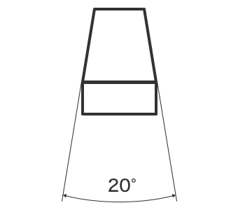
Adding a taper shape to a design is called tapering. A large taper angle is called a sharp taper, and a small taper angle is called a gentle taper. Slope is a term that is similar to taper, and it is necessary to use each of these terms correctly.
Difference between taper and slope
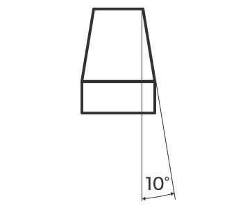
A shape having an inclination angle on both sides is a taper, while a shape having an inclination angle on one side while the other side is flat is a slope. For example, looking at the same circular cone shape, when describing the inclination of one side only using the center line as reference, then it is a slope. When describing the inclination of both sides, then it is a taper.
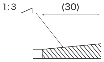
Drawing notation for taper and slope
Taper and slope are each indicated by a symbol and numeric value. Taper size is indicated by the taper angle or taper ratio. Slope is indicated by a number called the gradient ratio.
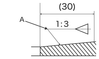
- A
- Align the taper symbol in the same direction as the taper shape.
Parts Where Tapers Are Used
Tapers are used in large numbers of parts such as bearings that support pins or shafts, pipes, and heat sinks or flanges. The shapes are all tapered, however their purposes are different, and their shapes have different characteristics.
Screws, bearings, fitting parts, etc.
These parts use a taper (linear taper) which changes the diameter linearly over distance. The side angle is constant, and the taper size is indicated by the taper angle or taper ratio.
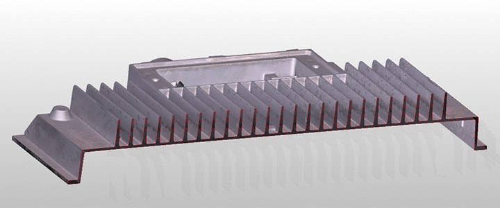
Engine cooling fins and heat sinks
These parts use a taper (exponential taper) which changes the diameter exponentially over distance. The side shape narrows more rapidly at distances farther away from the base, and the tip is very sharp. This makes it possible to reduce the pitch and also reduce weight and vibration.
In addition, a taper with a parabolic shape (parabolic taper) is used in parts intended to reduce fluid resistance such as pipes and aircraft bodies. In parts such as pins which are used to join other parts together, a reverse taper is used. A reverse taper has a shape that is inverted from a regular taper and has a tip that is thicker than the base.
Calculating Taper Angle
In drawings, the taper size is usually indicated by the taper ratio. However in cases such as when machining using a lathe, the value of the taper angle may be required.
Taper ratio
This is the ratio of the thick end dimension to the thin end dimension. For example, when the taper ratio is 3:100, the diameter becomes thinner by 3 mm (0.12") per 100 mm (3.94") of length.
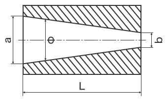
- a
- Larger side diameter
- b
- Smaller side diameter
- L
- Length
- Φ
- Taper angle
Taper angle
Taper angle can be calculated using the formula below.


For example, when the taper ratio specified in the drawing is 3/100, the taper angle can be calculated as shown below.

Taper Production Methods
Tapers are created by using a lathe or press. With press forming, the taper is created when making the die and that shape is then "pressed" onto a material. In the case of a lathe, machining is performed by adjusting the angle of the insert holder. Here we will introduce how a taper is created when using a lathe.
A lathe is a machine tool which removes material while it is being rotated. An insert or specialized cutting tool is applied to the surface of the object as it rotates, and material is removed circumferentially. Because cutting is performed while the workpiece is rotating, this method is suitable for machining tapers where the diameter becomes thinner towards the tip. With a lathe, the angle of the tapered end mill is specified as 1/2 of the taper angle. 1/2 of the taper angle is equal to the slope angle.
(1) Rotate the lathe and adjust the angle.
↓
(2) Operate the handle of the lathe and perform cutting.
↓
(3) After cutting to the end, return until tool bit disengages.
↓
(4) Repeat this procedure until the desired shape is obtained.
When a high-precision lathe is used, fine taper processing on the order of micrometers is possible. Accordingly, high-accuracy measuring instruments are required for quality control.
Problems in Conventional Taper Measurement
It is extremely important to confirm that the dimensions and shapes produced by taper machining are within tolerances. In particular, because a conical taper is a three-dimensional shape, high accuracy and quantitative 3D measurement is required. However, there are various problems in measurement when using conventional optical comparators, profile measurement systems, and taper gauges. Such issues can include difficulty in achieving accurate measurement and variation in measured values.
Problems in taper measurement using an optical comparator
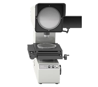
An optical comparator is a type of optical measuring instrument with a similar measurement principle to an optical microscope. An object is placed on a stage and the measuring instrument transmits light from below, projecting the target profile onto a screen. Some large optical comparators have screen diameters that are larger than 1 m (3.3'). For parts with recessed tapers, the profile cannot be visualized with this method without cutting the sample first.
This measurement method involves the following problems.
- With an ordinary optical comparator lens, only a part of the target is in focus. For this reason, it is necessary to focus precisely on each measurement point manually. For example, when the target is a circular cone, it is necessary to precisely adjust the focus at each measurement location. This not only results in the problem of measurement error when the focus position differs depending on the operator, but also the problem of longer times required to adjust the focus when measuring more locations. It may also be necessary to cut the target in order to measure the cross-sectional shape.
- When comparing shapes, it is necessary to visually check the differences by overlaying the projection with a 10× enlarged drawing. Differences between the projected dimensions and the drawing cannot be obtained in numerical form, and the profile shape must be transferred to tracing paper, making it difficult to store and compare the data.
This results in a number of large problems. Not all on-site operators are capable of accurately measuring shapes. There are also some locations which cannot be measured, and it may be necessary to cut the target.
Problems in taper measurement using a profile measurement system
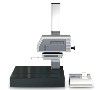
A profile measurement system measures and records the profile of a target by tracing its surface with a stylus. In recent years, profile measurement systems have been developed that use a laser instead of a stylus to measure complex shapes by tracing the profile in a non-contact manner. Some models are even able to perform measurement of both the top and bottom surfaces.
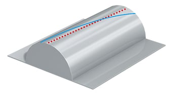
A profile measurement system must trace an accurate measurement line in the perpendicular direction relative to the target taper shape.
This involves the following problems.
- Measurement work requires much time, including time for fastening the sample to the jig and leveling it. Knowledge and skills related to using profile measurement systems are also required in order to level a target accurately.
- The stylus of a profile measurement system moves up and down in an arc centered on the fulcrum of the stylus arm, and the tip of the stylus also moves in the X-axis direction. This produces error in the X-axis data.
- Tracing the desired line with the stylus is extremely difficult work, and even slight displacement of the stylus produces error in the measured values.
Solution to Problems in Taper Measurement
Reviewing the problems of conventional measuring instruments shows that there is a certain point which the problems all have in common. This is that measurement of a three-dimensional target or area is done by means of point and line contact.
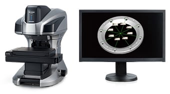
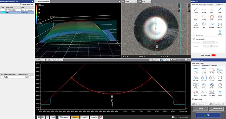
To resolve these measurement problems, KEYENCE has developed the 3D Optical Profilometer VR Series. The VR Series accurately captures the 3D shape of the entire target surface without contacting the target. It also measures the 3D shape by 3D-scanning the target on the stage in as little as one second with high accuracy. This allows instantaneous quantitative measurement that is free of variation in the measurement results. Some specific examples of the advantages are explained below.
Advantage 1: Measure without cutting the target
With a contact-type measuring instrument, because the probe cannot reach all the way to the bottom, it is difficult to measure targets where the pitch is small and there are recesses, such as blade tools and heatsink fins.
The VR Series can measure tapers and other shapes by virtually cross-sectioning the object, something which previously required actual cutting of the object in order to perform. Even objects with recessed areas can be measured without destroying them.
Users can also create templates for commonly measured items in order to streamline the measurement process and rapidly analyze multiple parts.

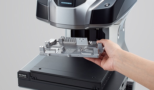
Advantage 2: Measure a large area of up to 300 mm x 150 mm (11.81" × 5.91")
Measurement can be performed simply by placing the target on the stage and pressing a button. Strict positioning or other preparation is not necessary. The VR Series is able to extract features from the object and automatically adjust the alignment of the part. This makes it possible to perform highly accurate measurement by operators who do not have knowledge or experience related to measuring instruments.
Summary: Dramatic Improvement and Higher Efficiency in Measurement of Tapers
The VR Series resolves the problems faced by conventional measuring instruments by instantaneously measuring 3D objects with high-accuracy, non-contact 3D scanning.
- Measure cross-sections without cutting the target.
- Eliminate variations resulting from human factors, making true quantitative measurement possible.
- Without the need for accurate positioning or other preparation, measurement can be performed simply by placing the target on the stage and pressing a button. This eliminates the need to assign a specialized operator for measurement work.
- 3D shapes can be measured easily at high speeds with high accuracy. This makes it possible to measure a large number of targets in a short time, helping to improve quality.
This system also allows comparisons with past 3D measurements and CAD data, as well as easy data analysis such as distribution within tolerances. It can be used effectively for a wide range of purposes including product development, manufacturing trend analysis, and sampling inspections.
