A Solution to Problems in Die Wear Measurement
Dies are essential in the forming of products such as automobile parts, construction materials, commodities, and electronic components. Because reducing the die production cost and extending the service life are linked directly to product cost and quality, improvements in die engineering are extremely important for improving our everyday lives.
As dies are essential to forming of a wide range of materials, this page will consider the wear which occurs when dies are used, and will explain countermeasures for extending die service life based on the knowledge which is currently available. It will also introduce the methods of measuring die wear, problems in conventional measurement methods, and a solution to these problems.
- Die Wear
- Countermeasures to Abnormal Wear
- Problems in Conventional Die Wear Measurement
- Solution to Problems in Die Wear Measurement
- Summary: Dramatic Improvement and Higher Efficiency in Difficult Die Wear Measurement
Die Wear
Die wear is a phenomenon in which the surface of a die becomes worn as a result of friction between parts as the die is continuously used. Die wear is classified into “Abnormal wear” and “Normal wear.” Abnormal wear is caused by inappropriate material or shape, metal fatigue, and corrosion. Normal wear is caused by part contact or friction that gradually reduces the die surface.
Abnormal wear
Abnormal wear can lead to fatal damage such as operation failure of or damage to the die cavity or core. Typical types of abnormal wear include the following five types. Among these types of abnormal wear, abrasive wear and adhesive wear occur most frequently with dies, and the wear mode of these two types is called galling.
- Abrasive wear:
- Abrasive wear is classified into two-body wear and three-body wear. Two-body wear occurs when a harder material digs into a softer material. Three-body wear occurs when the die surface is mechanically ground away by hard wear powder (hard particles). This wear mode is called ploughing.
-
Two-body wear 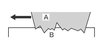
- A
- Harder material
- B
- Softer material
Three-body wear 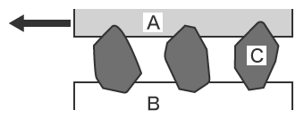
- A
- Harder material
- B
- Softer material
- C
- Hard particles
- Adhesive wear:
- Adhesive wear is a wear phenomenon in which contacting protruding parts adhere to one another, and the adhering parts then become separated from the surface. It is also called seizure.
-
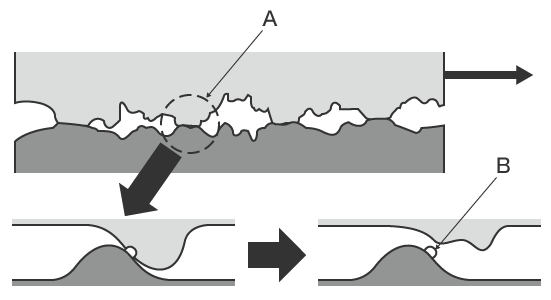
- A
- Contacting parts
- B
- Adhesion and separation
- Fatigue wear:
- This type of wear occurs due to metal fatigue resulting from repeated operating starts and stops. Repeated stress causes work hardening of the surface, which creates fine cracks over time. These small cracks eventually progress to form larger cracks, resulting in separation of the surface. The shearing stress which produces the fine cracking is highest at a point slightly below the surface. The larger cracks form starting from this point. Separation of fish scale shapes (flaking) or large sheets (peeling) can occur.
- Fretting wear:
- This wear forms minute pitting of the surface as a result of repeated small movement (fretting) that produces friction force at the surfaces of parts that are fit together. Fine cracking occurs on a surface where fretting wear occurs. Because external load and fretting friction force are applied in combination at these locations, fatigue strength is reduced to half or less of the original level, and may result in fatigue fracture.
- Corrosion wear:
- This wear occurs when surface material is removed at a sliding part due to an electrical potential difference between the metals that is generated in a corrosive atmosphere. The addition of friction further accelerates the wear damage. This is also referred to as chemical wear. It occurs due to the mechanical action of friction and the chemical reaction with a gas or liquid atmosphere. When this type of wear occurs in a liquid atmosphere, it is also referred to as erosion-corrosion.
Normal wear
This wear occurs during normal use in cases when neither abrasive wear nor adhesive wear occurs. Normal wear is classified into initial wear and steady state wear. Initial wear is also called fitting wear, and it occurs when fine surface irregularities are removed from the materials after the start of operation. Steady state wear is normal wear that occurs over continued use. By replacing a part with a new part when it reaches the set dimension used for normal wear management, it is possible to prevent die failures and defects.
Countermeasures to Abnormal Wear
This section explains the countermeasures to abrasive wear and adhesive wear, which are typical modes of abnormal die wear.
Countermeasures to abrasive wear
Abrasive wear countermeasures are different for two-body wear and three-body wear.
- Two-body wear:
- Possible countermeasures for two-body wear include increasing the material hardness and using a steel type which contains large amounts of carbides. Because abrasion resistance generally is higher when the surface is harder, performing quenching, nitriding, or similar treatment of the die is also effective.
- Three-body wear:
- To prevent three-body wear, completely seal the sliding surfaces of the machine in order to prevent the entry of sand or other grinding particles. One effective countermeasure is installing a filter in the lubrication system so that such particles can be removed quickly if they enter the system.
Countermeasures to adhesive wear
Possible countermeasures to adhesive wear include using a die material that has the necessary hardness and toughness. However in fact there are limits to countermeasures which can be carried out only by improving the die material. For this reason, it is necessary to enact countermeasures that prevent adhesion by reducing the coefficient of friction between the die surface and the workpiece. Optimizing lubrication is particularly important, and it is necessary to apply lubricant uniformly, design dies to prevent lubricant from running out, and optimize the processing conditions. Hard surface treatment to reduce the coefficient of friction is also effective.
Problems in Conventional Die Wear Measurement
It is extremely important to verify that die wear is within tolerances. In particular with dies that are used for forming at high pressure, accurate and quantitative 3D shape measurement is needed.
Conventional measurement of die wear uses profile measurement systems or coordinate measuring machines. However there are various problems in measurement using a conventional coordinate measuring machine or profile measurement system. These include the high level of difficulty required to obtain accurate measurements, and variation in the measured values. Quantification of the measured data is also difficult, and trend analysis and other analysis related to die aging is problematic.
Problems in die wear measurement using a profile measurement system
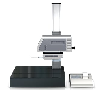
A profile measurement system measures and records the profile of a target by tracing its surface with a stylus. In recent years, profile measurement systems have been developed that use a laser instead of a stylus to measure complex shapes by tracing the profile in a non-contact manner. Some models are even able to perform measurement of both the top and bottom surfaces.
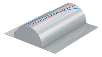
A profile measurement system must trace an accurate measurement line for the measurement points.
This involves the following problems.
- Measurement work requires much time, including time for fastening the die to a jig and leveling it. Knowledge and skills related to using profile measurement systems are also required in order to level a target accurately.
- The stylus of a profile measurement system moves up and down in an arc centered on the fulcrum of the stylus arm, and the tip of the stylus also moves in the X-axis direction. This produces error in the X-axis data.
- Tracing the desired line with the stylus is extremely difficult work, and even slight displacement of the stylus produces error in the measured values.
- Only part of a target can be measured, and evaluation of the entire surface is not possible.
Problems in die wear measurement using a coordinate measuring machine
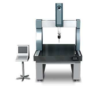
Typical coordinate measuring machines measure shapes by “scanning” that uses a contact probe to trace and measure the shape. This kind of scanning measures large numbers of points at a specified pitch.
However this measurement method involves the following problems.
- From straight lines along the center of a cylinder or curved surface to lines passing through the center of a circle, ensuring that the probe moves as intended is an extremely difficult task. In the case of a rounded corner with a small center angle, because the entire circle is calculated from a short arc, even a small error in measurement will be magnified largely. Such deviations in the measurement points can result in slight variation in the measured values.
- When measuring a small 3D shape, the probe may be unable to contact the measurement positions. Because measurement accuracy is proportional to the number of points or lines that are measured, it is necessary to measure a large number of points or lines.
In this way, measurement using a coordinate measuring machine involves significant problems, including the fact that not all workplace operators can accurately measure shapes, the existence of parts that cannot be measured at all, and limited locations where the machine can be installed.
Solution to Problems in Die Wear Measurement
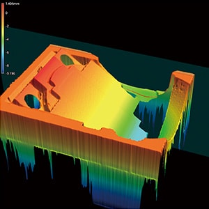
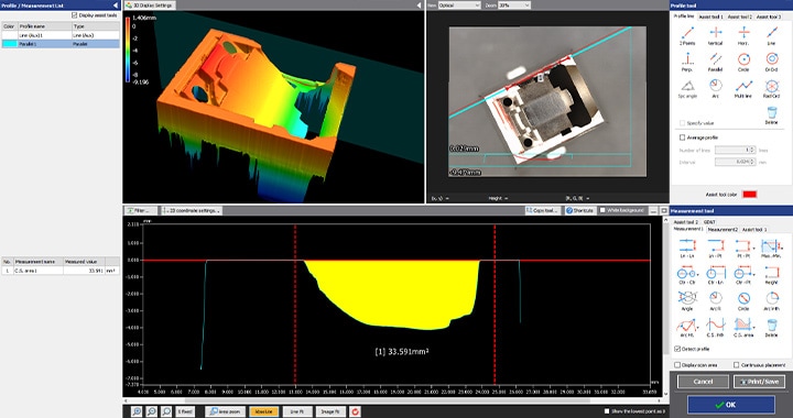
The measuring instruments that are ordinarily used involve problems such as the long time required to position the target, and the fact that measurement of three-dimensional targets and areas is performed by means of point or line contact. To resolve these measurement problems, KEYENCE has developed the 3D Optical Profilometer VR Series.
The VR Series accurately captures the 3D shape of the entire target surface without contacting the target. It also measures the 3D shape by 3D-scanning the target on the stage in as little as one second with high accuracy. It is capable of instantaneous and quantitative measurement with no errors in the measurement results. This section introduces some specific advantages of the VR Series.
Advantage 1: Measure a large number of points in as little as one second
The VR Series acquires surface data (800,000 points) for the 3D target shape in as little as one second, dramatically reducing the time required for measuring large numbers of points. It accurately and instantaneously measures the maximum and minimum irregularities on the entire target surface, enabling rapid evaluation of all locations on the target based on the preset tolerances. This makes it possible to manage difficult-to-define states such as the amount of wear or chipping.
Once a workpiece has been scanned, its profile (cross-section) can also be measured at locations different from the locations used in past measurement. This eliminates the need to set and measure the same target again.

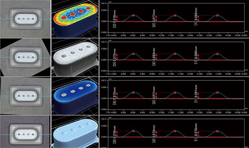
Advantage 2: Compare measurements between parts or against CAD data
The VR Series is capable of more than just efficiently collecting data. Measurement data can be displayed in a list, and the same analysis contents can be applied to all data at the same time.
For example, it is possible to measure the shapes of products produced using both a new die and old die, and to identify the differences in the shape resulting from the dies. In addition, it is also possible to load CAD data in order to quickly identify how much a failed product differs from a good product. This enables easy quantitative analysis and evaluation of die wear.
The VR Series can quickly measure targets that have complex shapes, something which previously required much labor and time. All measurement results are digital, significantly reducing the work required for subsequent data comparison and analysis.
Summary: Dramatic Improvement and Higher Efficiency in Difficult Die Wear Measurement
The VR Series is capable of quickly measuring and quantifying the amount of wear on a die, a measurement that had previously required a lot of experience, was time-consuming, or was impossible to do for complex dies. As a result, the VR Series can evaluate product quality with a higher level of accuracy and efficiency.
- Because the entire surface is measured, data for a large number of points is acquired simultaneously. This can significantly reduce the time required for measurement of complex shapes.
- With the VR Series, multiple sets of measurement data can be displayed in a list for comparison, allowing various differences in deformation caused by wear to be identified and analyzed.
- By scanning a product formed by pressing and comparing the measured data with CAD data, it is possible to accurately identify the conditions of die wear.
- This eliminates variation resulting from human factors, making true quantitative measurement possible.
- Without the need for positioning or other preparation, measurement can be performed simply by placing the target on the stage and pressing a button. This eliminates the need to assign a specialized operator for measurement work.
- 3D shapes can be measured easily at high speeds with high accuracy. This makes it possible to measure a large number of targets in a short time, helping to improve quality.
This system also allows comparisons with past 3D shape data, as well as easy data analysis such as roughness distribution. It can be used effectively for a wide range of purposes including trend analysis of die wear over time and checking the conditions of material loss.
