A Method for Accurate and Easy Measurement of Wear
Wear occurs at tool bit edges, the sliding portions of mechanical parts, and has a large effect on performance. The effects of wear may cause machining failure (due to heat or vibration), operation failure (caused by looseness), and in the worst case may lead to machine malfunction or damage.
Oil or other lubricants can be used to prevent wear. However, wear is difficult to completely prevent and remains a potential risk factor. For this reason, measurement of wear is essential in order to maintain product quality, carry out equipment maintenance, and ensure safety.
- Wear
- Types of Wear
- Necessity of Wear Measurement
- Problems in Conventional Wear Measurement
- Solution to Problems in Wear Measurement
- Summary: Dramatic Improvement and Higher Efficiency in Difficult Wear Measurement
Wear
Wear occurs when the material of a solid surface is gradually removed as a result of friction. Friction and wear are affected by external factors (such as load, speed, temperature, and atmosphere) as well as engineering factors (such as geometric shape, deformation, and interface state).
Erosion is similar to wear, and refers to wear caused by friction between a fluid and a solid object. For example, erosion can occur between the fluid in a pipe and the pipe walls.
Types of Wear
Because wear occurs as a result of an extremely large number of parameters interacting in complex ways. This includes the location of friction, physical characteristics of friction materials, the ambient atmosphere, heat, temperature, and physical and chemical actions. This section introduces some typical types of wear.
Adhesive wear
Adhesive wear occurs when two solid objects rub against each other and become joined together (adhered), then fracture and separate. Adhesive wear occurs as a result of chemical bonds between the solid objects. For this reason, it is more likely to occur between the following kinds of solid objects.
- Materials of the same type
- Materials which have the same crystalline structure and similar lattice constants
Abrasive wear
Abrasive wear occurs between two solid objects when the protrusions on the harder material mechanically cuts away the softer material. Characteristics include comparatively good lubrication conditions and low degree of adhesion, as well as a larger amount of wear compared with other wear modes.
Fatigue wear
Fatigue wear occurs when rolling friction is dominant over sliding friction, in cases such as on the rolling surface of a bearing or on a gear tooth surface. The process leading to fatigue friction is as shown below.
- (1) Repeated stress acts on the surface where metal parts contact each other.
- (2) This repeated stress causes the surface to gradually harden.
- (3) Fine cracking occurs, and progresses to form larger cracks.
- (4) The surface layer becomes peeled off.
The shearing stress which generates fine cracking in (3) is largest at a point slightly inside from the surface. The same process as above also results in pitting, which forms patch-like pits on a bearing surface as a result of rolling fatigue, as well as spalling, which causes considerably large metal fragments to fall off from the tooth surface as a result of material fatigue.
Fretting wear
Fretting wear is a wear that occurs at the contact surface between materials which were designed based on the assumption that no slipping would occur. When repeated stress is applied to parts fastened by bolts and nuts (or to the contact surfaces of two parts), slight relative slipping (fretting) occurs and causes wear. Fine cracking occurs on the surface where fretting wear is generated. Because external load and repeated stress act on the location of fretting wear, fatigue strength is reduced to half or less of the original level (fretting fatigue), resulting in fatigue fracture.
Necessity of Wear Measurement
Wear of machining tools is directly related to machining quality, and wear of parts is directly related to operation accuracy and safety. For this reason, it is extremely important to measure wear conditions such as the amount of wear. In this section, we will explain the importance of wear measurement using a brake pad and cutting tool bit as examples.
Measurement of brake pad wear
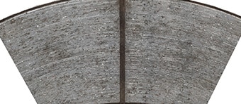
A new automobile brake pad is approximately 10 mm (0.39") thick. Although the timing varies depending on the manufacturer, generally the brake pad is replaced when it is worn down to around 1 to 3 mm (0.04" to 0.12"). The brake pad is worn by friction with the disc rotor in the case of a disc brake, or by friction with the brake drum in case of a drum brake. The disc rotor and brake drum also become worn. Because the wear conditions appear on the worn surface of the brake pad, the durability of the brake pad and the type of wear occurring during braking can be identified by measuring or observing the brake pad volume and amount of wear.
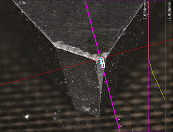
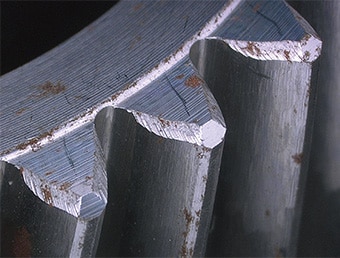
Measurement of tool bit wear
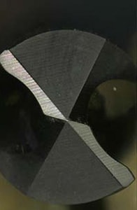
The tip of an end mill or tool bit becomes worn due to friction with the workpiece and cutting chips. The parts which become worn differ depending on the material; however, in most cases wear occurs on the rake surface and relief surface. Possible causes are a cutting speed that is too high or an unsuitable tool bit material. Because the load on tool bit increases when machining a material that is a difficult to cut, the amount of wear is larger than when machining ordinary materials. Caution is required because friction on the relief surface can increase the cutting force or change the cutting depth.
For these reasons, measurement of tool bit wear is extremely important for evaluating cutting speed and for the selection of tool bit material.
Problems in Conventional Wear Measurement
Typically, the amount of wear is measured using profile measurement systems or coordinate measuring machines. However, these methods involve the following measurement problems when measuring wear over a large area or on small parts.
Problems in wear measurement using a profile measurement system
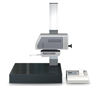
A profile measurement system measures and records the profile of a target by tracing its surface with a stylus. In recent years, profile measurement systems have been developed to use a laser instead of a stylus to measure complex shapes by tracing the profile in a non-contact manner. Some models are even able to perform measurement of both the top and bottom surfaces.
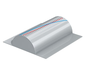
A profile measurement system must trace an accurate measurement line for the amount of wear that is the measurement target.
This involves the following problems.
- Measurement work requires much time, including time for fastening the sample to the jig and leveling it. Knowledge and skills related to using profile measurement systems are also required in order to level a target accurately.
- The stylus of a profile measurement system moves up and down in an arc centered on the fulcrum of the stylus arm; the tip of the stylus also moves in the X-axis direction producing error in the X-axis data.
- Tracing the desired line with the stylus is extremely difficult work, and even slight displacement of the stylus produces error in the measured values.
- It is also difficult to increase the number of targets because of the need to pinpoint specific locations for measurement.
- Only part of a target can be measured, and evaluation of the entire surface is not possible.
Problems in measurement using a coordinate measuring machine
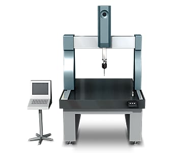
When the area of the worn part is small, for example 1 mm2, it is extremely difficult to measure the shape accurately by pinpointing the surface with a probe and creating a virtual surface. It is also difficult to identify the accurate 3D shape when measuring a small area due to the small number of measurement points. Much work is also involved with related tasks such as tabulating the measurement data and comparing the results with the drawings.
Solution to Problems in Wear Measurement
Conventional measuring instruments measure a three-dimensional target or area by means of point and line contact. This produces problems because users cannot identify the entire shape, and the reliability of the measured values is low. To resolve these measurement problems, KEYENCE has developed the VR Series 3D Optical Profilometer.
The VR Series accurately captures the 3D shape of the entire target surface without contacting the target. It also measures the 3D shape by 3D-scanning the target on the stage in as little as one second with high accuracy. It is capable of instantaneous and quantitative measurement with no errors in the measurement results. This section introduces some specific advantages of the VR Series.
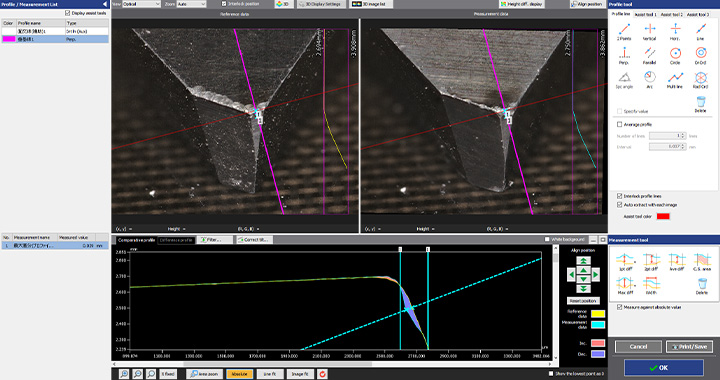
Advantage 1: Collect data from 800,000 measurement points in as little as one second.
The VR Series measures the entire surface shape and collects data from a group of 800,000 points. Because measurement is not performed using lines or points, repeat measurement is not required, reducing measurement time. Items that are difficult to define, such as the amount of wear, can be evaluated based on volume or surface area. It is also possible to easily perform quantitative evaluation of flatness. The VR Series can also measure profiles at specific locations. Even after measurement, profiles of different parts can be acquired from the 3D scan data without scanning the target again.
All measurement data is stored, and the stored data can be compared with other data or with 3D design data.

Advantage 2: Capable of measuring a wide area of up to 300 mm x 150 mm (11.81" × 5.91").
Measurement can be performed simply by placing the target on the stage and pressing a button. Strict positioning or other preparation is not necessary. This makes it possible to perform highly accurate measurement by operators who do not have knowledge or experience related to measuring instruments.
Because the VR Series extracts the features of the target on the stage and automatically corrects its position, strict positioning requiring much time and effort is not necessary. The VR Series can also measure a wide area of up to 300 mm x 150 mm (11.81" × 5.91") by stitching multiple measurement images. This makes it possible for even an inexperienced operator to easily and instantaneously perform measurement, and eliminates the need to assign a specialized operator to measurement work.
With the VR Series can accurately measure a large surface area, such as a large brake pad, simply by placing the target on the stage and pressing a button.
Summary: Dramatic Improvement and Higher Efficiency in Difficult Wear Measurement
The VR Series can measure 3D target shapes accurately and instantaneously by high-speed 3D scanning without contacting the target. It resolves all the problems faced by conventional measuring instruments by allowing measurement of the highest and lowest points on the wear surface as well as measurement of volume, cross-section area, and ratio of surface area to cross-section area.
- It is capable of simultaneously measuring the highest point, lowest point, area, volume, and surface area accurately.
- This eliminates variation resulting from human factors, making true quantitative measurement possible.
- Without the need for positioning or other preparation, measurement can be performed simply by placing the target on the stage and pressing a button. This eliminates the need to assign a specialized operator for measurement work.
- 3D shapes can be measured easily at high speeds with high accuracy. This makes it possible to measure a large number of targets in a short time, helping to improve quality.
This system also allows comparisons with past 3D shape data and CAD data, as well as easy data analysis such as distribution within tolerances. It can be used effectively for a wide range of purposes including product development, manufacturing trend analysis, and sampling inspections.
