Programmable Logic Controller
KV-8000 series
Specs Programmable Logic Controller KV-8000 series
CPU unit
|
Model |
KV-8000A |
|||
|
Image |
|
|||
|
General specifications |
Power voltage |
System configuration using an expansion unit for KV-5000/3000 Series: 24 VDC (±10%) |
||
|
Operating ambient temperature |
System configuration using an expansion unit for KV-5000/3000 Series: 0 to +50°C 32 to 122°F (No freezing) |
|||
|
Operating ambient humidity |
System configuration using an expansion unit for KV-5000/3000 Series: 10 to 95% RH (No condensation) |
|||
|
Storage ambient temperature |
System configuration using an expansion unit for KV-5000/3000 Series: -20 to +70°C -4 to +158°F |
|||
|
Storage relative humidity |
System configuration using an expansion unit for KV-5000/3000 Series: 10 to 95% RH (No condensation) |
|||
|
Operating environment |
No dust or corrosive gas |
|||
|
Operating altitude |
2000 m 6561.7' or less |
|||
|
Noise immunity |
1500 Vp-p or more |
|||
|
Withstand voltage |
1500 VAC, 1 minute (between the power supply terminal and the I/O terminals and between the external terminals and the case) |
|||
|
Insulation resistance |
50 MΩ or more (between the power terminals and the I/O terminals, and between the external terminals and the case, with 500 VDC megohmmeter) |
|||
|
Vibration resistance |
Intermittent vibration |
Frequency 5 to 9 Hz |
Half amplitude 3.5 mm 0.14"*1 |
|
|
Frequency 9 to 150 Hz |
Acceleration 9.8 m/s2 32.2'/s2*1 |
|||
|
Continuous vibration |
Frequency 5 to 9 Hz |
Half amplitude 1.75 mm 0.07"*1 |
||
|
Frequency 9 to 150 Hz |
Acceleration 4.9 m/s2 16.1'/s2*1 |
|||
|
Internal current consumption |
400 mA or less*2 |
|||
|
Shock resistance |
Acceleration 150 m/s2 492.1'/s2, Operation time 11 ms, twice in each of the X, Y and Z directions |
|||
|
Overvoltage category |
I (II when using KV-PU1) |
|||
|
Pollution degree |
2 |
|||
|
Weight |
KV-8000A: Approx. 340 g |
|||
|
Performance specifications |
Arithmetic control mode |
Stored program mode |
||
|
I/O control mode |
Refresh mode |
|||
|
Program language |
Expanded ladder, KV Script, mnemonic |
|||
|
Number of commands |
Basic instructions: 80 classes, 181 instructions |
|||
|
Instruction execution speed |
Basic instructions: Min. 0.96 ns |
|||
|
CPU memory capacity |
64 MB |
|||
|
Program capacity |
Approx. 1500 k steps |
|||
|
Maximum number of units to be installed |
16 units (KV-8000/7000 Series expansion unit only) |
|||
|
Maximum number of I/O points |
Maximum 3072 points for expansion |
|||
|
Bit device |
Input relay R |
Total 32000 points 1 bit |
||
|
Output relay R |
||||
|
Internal auxiliary relay R |
||||
|
Self-diagnosis function |
CPU error, RAM error, other |
|||
|
Bit device |
Link relay B |
32768 points 1 bit |
||
|
Internal auxiliary relay MR |
64000 points 1 bit |
|||
|
Latch relay LR |
16000 points 1 bit |
|||
|
Control relay CR |
1280 points 1 bit |
|||
|
Word device |
Timer T |
4000 points 32 bits |
||
|
Counter C |
||||
|
Data memory DM |
65535 points 16 bits |
|||
|
Expansion data memory EM |
||||
|
File register |
Current bank FM |
524288 points 16 bits |
||
|
Dial mode ZF |
||||
|
Link register W |
32768 points 16 bits |
|||
|
Temporary memory TM |
512 points 16 bits |
|||
|
Index register Z |
12 points 32 bits |
|||
|
Control memory CM |
7600 points 16 bits |
|||
|
Number of comments/ labels stored in main unit |
Device comment |
Approx. 224000 |
||
|
Label |
Approx. 285000 |
|||
|
Power failure hold function |
Program memory |
Flash ROM can be written 10000 times |
||
|
Device |
Nonvolatile RAM |
|||
|
Calendar timer |
Backup condenser lasts approx. 15 days (at 25°C 77°F) |
|||
|
*1 Compliant with JIS B 3502 and IEC61131-2, No. of scans: 10 times in each of X, Y, and Z directions (for 100 min.) |
||||

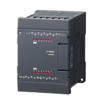
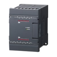
Input Unit
|
Model |
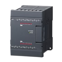
KV-B16XC |
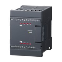
KV-C32XC |
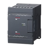
KV-C64XC |
|||
|
Image |
|
|
|
|||
|
Type |
Input Unit |
|||||
|
External connection method |
Removable terminal block |
Connector (MIL standard)*3 |
||||
|
Input |
Number of inputs |
16 points |
32 points |
64 points |
||
|
Input mode |
24 VDC mode, 5 VDC mode |
24 VDC mode*4 |
||||
|
Maximum input voltage |
26.4 VDC |
|||||
|
Rated input voltage |
24 VDC mode: 24 VDC, 5.3 mA, 5 VDC mode: 5 VDC, 1 mA |
24 VDC, 4.1 mA |
||||
|
Minimum ON voltage |
24 VDC mode: 19 V, 5 VDC mode: 3.5 V |
19 V |
||||
|
Maximum OFF current |
24 VDC mode: 1.5 mA |
1.5 mA |
||||
|
Maximum OFF voltage |
5 VDC mode: 1.5 V |
- |
||||
|
Common method |
16 points/1 common (2 terminals)*1 |
32 points/1 common (2 terminals)*1 |
32 points/1 common (2 terminals) × 2*5 |
|||
|
Input time constant |
[Input time constant setting 25 µs] OFF to ON: Typ. 25 µs/Max. 65 µs, ON to OFF: Typ. 75 µs/Max. 120 µs |
|||||
|
Input impedance |
4.3 kΩ |
5.6 kΩ |
||||
|
Internal current consumption |
15 mA or less |
25 mA or less |
||||
|
Weight |
Approx. 120 g |
Approx. 110 g |
Approx. 140 g |
|||
|
*1 Even though KV-B16XC and KV-C32XC have two common points, they are the same internally. |
||||||


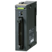
Output unit
|
Model |
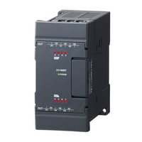
KV-B16TCP |
KV-C32TCP |
KV-C64TCP |
|||
|
Image |
|
|
|
|||
|
Type |
Output unit |
|||||
|
External connection method |
Removable terminal block |
Connector (MIL standard)*2 |
||||
|
Output |
Number of outputs |
16 points |
32 points |
64 points |
||
|
Output mode |
Transistor (source) |
|||||
|
Rated load |
30 VDC, 0.2 A |
|||||
|
Leakage current at OFF |
100 μA or less |
|||||
|
Residual voltage at ON |
0.5 V or less |
|||||
|
ON resistance |
- |
|||||
|
Common method |
16 points/1 common (2 terminals)*1 |
32 points/1 common (2 terminals)*1 |
64 points/1 common (4 terminals)*3 |
|||
|
Operation time |
OFF to ON: 10 μs or less,ON to OFF: 200 μs or less |
OFF to ON: 50 μs or less,ON to OFF: 200 μs or less |
||||
|
Internal current consumption |
30 mA or less |
55 mA or less |
100 mA or less |
|||
|
Weight |
Approx. 130 g |
Approx. 100 g |
Approx. 140 g |
|||
|
*1 Although KV-B16TD, KV-C32TD, KV-B16TCP, and KV-C32TCP have two points, they are the same internally. |
||||||


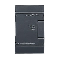
Output unit
|
Model |
KV-B8RC |
KV-B16RC |
KV-B16TD |
KV-C32TD |
KV-C64TD |
|||
|
Image |
|
|
|
|
|
|||
|
Type |
Output unit |
|||||||
|
External connection method |
Removable terminal block |
Connector (MIL standard)*2 |
||||||
|
Output |
Number of outputs |
8 points |
16 points |
32 points |
64 points |
|||
|
Output mode |
Relay |
MOSFET (sink) (with overcurrent protection function) |
||||||
|
Rated load |
250 VAC/30 VDC, 2 A |
250 VAC/30 VDC, 2A (8 A/1 common) |
30 VDC, 0.3 A |
30 VDC, 0.2 A |
||||
|
Leakage current at OFF |
- |
100 μA or less |
||||||
|
Residual voltage at ON |
0.5 V or less |
|||||||
|
ON resistance |
50 mΩ or less |
- |
||||||
|
Common method |
Independent |
8 points/1 common |
16 points/1 common (2 terminals)*1 |
32 points/1 common (2 terminals)*1 |
64 points/1 common (4 terminals)*3 |
|||
|
Operation time |
OFF to ON/ON to OFF: 10 ms or less |
OFF to ON: 100 μs or less,ON to OFF: 300 μs or less |
OFF to ON: 150 μs or less,ON to OFF: 300 μs or less |
|||||
|
Internal current consumption |
65 mA or less |
120 mA or less |
45 mA or less |
65 mA or less |
120 mA or less |
|||
|
Weight |
Approx. 160 g |
Approx. 190 g |
Approx. 130 g |
Approx. 100 g |
Approx. 140 g |
|||
|
*1 Although KV-B16TD, KV-C32TD, KV-B16TCP, and KV-C32TCP have two points, they are the same internally. |
||||||||


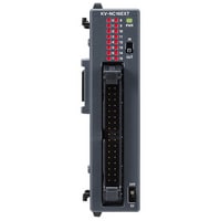
I/O unit
|
Model |
KV-B8XTD |
KV-C16XTD |
KV-C32XTD |
KV-SIR32XT |
|||
|
Image |
|
|
|
|
|||
|
Type |
I/O unit |
High-speed I/O unit |
|||||
|
External connection method |
Removable terminal block |
Connector (MIL standard)*2 |
Connector (MIL specification)*2 |
||||
|
Input |
Number of inputs |
8 points |
16 points |
32 points |
|||
|
Input mode |
24 VDC mode, 5 VDC mode |
24 VDC mode*3 |
24 VDC mode, 5 VDC mode*5 (with overvoltage protection function*6) |
||||
|
Maximum input voltage |
26.4 VDC |
24 VDC mode: 28.8 VDC |
|||||
|
Rated input voltage |
24 VDC mode:24 VDC, 5.3 mA , 5 VDC mode: 5 VDC, 1 mA |
24 VDC, 4.1 mA |
24 VDC mode: 24 VDC, 5.1 mA |
||||
|
Minimum ON voltage |
24 VDC mode:19 V , 5 VDC mode: 3.5 V |
19 V |
24 VDC mode: 19 V |
||||
|
Maximum OFF current |
24 VDC mode: 1.5 mA |
1.5 mA |
24 VDC mode: 1.5 mA |
||||
|
Maximum OFF voltage |
5 VDC mode: 1.5 V |
- |
5 VDC mode: 1.5 V |
||||
|
Common method |
8 points/1 common (1 terminal) |
16 points/1 common (1 terminal) |
32 points/1 common (2 terminals)*4 |
16 points/1 common (2 terminals)*7 |
|||
|
Input time constant |
25 μs/300 μs*1/1 ms/10 ms |
1 μs/10 μs/20 μs/100 μs/500 μs/1 ms/5 ms/10 ms/50 ms |
|||||
|
Input impedance |
4.3 kΩ |
5.6 kΩ |
24 VDC mode: 4.4 kΩ |
||||
|
Output |
Number of outputs |
8 points |
16 points |
32 points |
|||
|
Output mode |
MOSFET (sink) (with overcurrent protection function) |
MOSFET (sink) (with overcurrent protection function)*8 |
|||||
|
Rated load |
30 VDC, 0.3 A |
30 VDC, 0.2 A |
30 VDC, 0.2 A (1.6 A/1 common) |
||||
|
Leakage current at OFF |
100 μA or less |
||||||
|
Residual voltage at ON |
0.5 VDC or less |
||||||
|
Common method |
8 points/1 common (1 terminal) |
16 points/1 common (1 terminal) |
32 points/1 common (2 terminals)*4 |
16 points/1 common (2 terminals)*7 |
|||
|
Operation time |
OFF to ON:100 μs or less ,ON to OFF: 300 μs or less |
OFF to ON:150 μs or less , ON to OFF: 300 μs or less |
OFF to ON: 1 μs or less: (Load: 5 mA to 200 mA) |
||||
|
Internal current consumption |
30 mA or less |
40 mA or less |
65 mA or less |
130 mA or less |
|||
|
Weight |
Approx. 130 g |
Approx. 110 g |
Approx. 130 g |
Approx. 190 g |
|||
|
*1 Configurable only when KV-8000A/7500/7300/5500/5000/3000 is connected. Cannot be selected when connected to KV-1000/700. |
|||||||


High-speed analog input unit
|
Model |
KV-SAD04 |
|||
|
Image |
|
|||
|
Type |
High-speed analog input unit |
|||
|
Analog input points |
Input: 4 points (differential input) |
|||
|
Analog input range (resolution) |
Input voltage |
-10 to +10 V (0.5 mV 1/40000) |
||
|
Input current |
0 to 20 mA (1 μA 1/20000) |
|||
|
Input impedance |
Voltage: 1 MΩ, Current: 250 Ω |
|||
|
Conversion speed |
10 μs/ch |
|||
|
Conversion precision |
25°C ±5°C 77°F ±9°F: ±0.1% (±20 digit), |
|||
|
Insulation mode |
Between unit and CPU: Photocoupler and transformer insulation, Between channels: Non-insulation |
|||
|
Absolute maximum input |
Voltage: -15 V/+35 V, Current: 30 mA |
|||
|
Internal current consumption |
80 mA or less |
|||
|
Weight |
Approx. 130 g |
|||

High-speed analog output unit
|
Model |
KV-SDA04 |
|||
|
Image |
|
|||
|
Type |
High-speed analog output unit |
|||
|
Analog output points |
Output: 4 points |
|||
|
Analog output range (resolution) |
Output voltage |
-10 to +10 V (0.5 mV 1/40000) |
||
|
Output current |
0 to 20 mA (1 μA 1/20000) |
|||
|
Conversion speed |
10 μs/ch |
|||
|
Conversion precision |
25°C ±5°C 77°F ±9°F: ±0.1% (±20 digit), |
|||
|
Insulation mode |
Between unit and CPU: Photocoupler and transformer insulation, Between channels: Non-insulation |
|||
|
Minimum load resistance |
Voltage: 1 kΩ |
|||
|
Maximum load resistance |
Current: 500 Ω |
|||
|
Internal current consumption |
170 mA or less |
|||
|
Weight |
Approx. 140 g |
|||

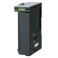
A/D and D/A conversion unit
|
Model |
KV-AM40V |
|||
|
Image |
|
|||
|
Type |
A/D and D/A conversion unit |
|||
|
Analog input points/output points |
Input: 2 points (differential input), Output: 2 points |
|||
|
Analog input range/output range (resolution) |
Voltage |
-10 to +10 V (1.25 mV 1/16000), -5 to +5 V*1 (0.625 mV 1/16000), |
||
|
Current |
0 to 20 mA (2.5 μA 1/8000), 4 to 20 mA (2.5 μA 1/6400) |
|||
|
Input resistance |
Voltage: 5 MΩ, Current: 250 Ω |
|||
|
Conversion speed |
80 μs/ch*2*3 |
|||
|
Conversion precision |
±0.2% of F.S. (at 25°C ±5°C 77°F ±9°F), ±0.4% of F.S. (at 0 to 50°C 32 to 122°F)*4 |
|||
|
Insulation mode |
Between unit and CPU: Photocoupler insulation |
|||
|
Absolute maximum input |
Voltage: ±15 V, Current: 30 mA |
|||
|
Minimum load resistance |
Voltage: 1 kΩ |
|||
|
Maximum load resistance |
Current: 600 Ω |
|||
|
Internal current consumption |
140 mA or less |
|||
|
Weight |
Approx. 150 g |
|||
|
*1 Analog output is not available for the range of -5 to +5 V. |
||||
Temperature control unit
|
Model |
KV-TF40 |
|||
|
Image |
|
|||
|
Type |
Temperature control unit |
|||
|
Memory elements |
EEPROM rewritable one million times |
|||
|
Number of temperature input points |
4 ch |
|||
|
Input |
Thermocoupler/Platinum temperature measuring resistor*1 |
|||
|
Temperature sensor types |
Thermocoupler: K, J, T, E, R, B, N, S, W5Re/W26Re |
|||
|
Indicated accuracy |
±0.3% of F.S. ±1 digit (at 25°C 77°F), ±0.7% of F.S. ±1 digit (at 0 to 50°C 32 to 122°F) |
|||
|
Cold junction correction precision |
±1°C ±1.8°F |
|||
|
Sampling cycle |
125 ms/ch (500 ms/4 ch) |
|||
|
Control period |
1 to 100 seconds |
|||
|
Operation mode |
PID control (with auto-tuning and 3 mode stabilizer function installed), |
|||
|
Tuning mode |
PID auto-tuning mode |
|||
|
Control output |
Transistor (sink) |
|||
|
Alarm output |
Transistor (sink)*2 |
|||
|
Alarm mode |
Absolute value upper limit, absolute value lower limit, deviation upper limit, deviation lower limit, deviation upper limit unexcited, |
|||
|
Output |
Rated load |
30 VDC, 100 mA or less |
||
|
Leakage current at OFF |
100 μA or less |
|||
|
Residual voltage at ON |
1.5 V or less |
|||
|
Current sensor (CT) input |
4 ch*4 |
|||
|
Current measurement precision |
Larger of ±5% of an input value and ±2 A of an input value |
|||
|
Insulation mode |
Between inputs and outputs: Photocoupler and transformer insulation, Between input channels: Photocoupler and transformer insulation |
|||
|
Others |
Heater wire breaking alarm, control loop wire breaking alarm, measured value |
|||
|
Internal current consumption |
210 mA or less |
|||
|
Weight |
Approx. 270 g |
|||
|
*1 Can be set for each channel. |
||||

Temperature/Analog multi-input unit
|
Model |
KV-TP40 |
|||
|
Image |
|
|||
|
Type |
Temperature/Analog multi-input unit |
|||
|
Number of temperature input points |
4 ch |
|||
|
Input |
Thermocoupler/Platinum temperature measuring resistor/Voltage and current |
|||
|
Input range |
Thermocoupler |
K: -270.0 to 1372.0°C -454 to 2502°F |
||
|
Platinum temperature measuring resistor |
Pt100: -200.0 to 850.0°C -328 to 1562°F |
|||
|
Voltage and current |
Voltage: |
|||
|
Indicated accuracy |
±0.2% of F.S. (at 25°C ±5°C 77°F ±9°F), ±0.4% of F.S. (at 0 to 50°C 32 to 122°F) |
|||
|
Cold junction correction precision |
±1°C ±1.8°F (during thermocouple input) |
|||
|
Input resistance |
Voltage: 1 MΩ, Current: 250 Ω |
|||
|
Conversion speed |
50 ms/4 ch |
|||
|
Insulation mode |
Between an input terminal and CPU: Photocoupler and transformer insulation, |
|||
|
Others |
External cold junction correction, wire-breaking detection function, scaling function, average processing function (time average, average of the number of times, moving average, primary delay filter), special data offset function, alarm function, rate of change calculation, rate of change alarm function |
|||
|
Internal current consumption |
90 mA or less |
|||
|
Weight |
Approx. 190 g |
|||

Positioning/Motion unit
|
Model |
KV-XH16EC |
KV-XH16ML |
KV-XH04ML |
|||
|
Image |
|
|
|
|||
|
Type |
Positioning/motion unit |
Positioning/Motion unit |
||||
|
No. of control axes |
16 axes (including virtual axes) |
16 axes (total including virtual axes) |
4 axes (total including virtual axes) |
|||
|
Appropriated device |
Relay: 2112 points (132 channels) |
Relay: 576 points (36 channels) |
||||
|
Output format |
EtherCAT ® |
MECHATROLINK-III |
||||
|
Connectable CPU unit |
KV-8000A/7500/7300 |
KV-8000A |
||||
|
Max. number of connectable units |
15 |
7 |
16 |
|||
|
Refresh |
Automatic refresh, direct refresh, synchronous refresh between units |
|||||
|
Control mode |
Position control, torque control, speed control, I/O control |
Positioning control, Torque control, Speed control, ML-III command, I/O control |
||||
|
Control period |
125 μs or more |
62.5 μs or more (With SV2 Series: 125 μs or more) |
500 μs or more |
|||
|
Starting time |
125 μs |
500 μs |
||||
|
Axis control function execution method |
Ladder program, unit program (flow) |
Ladder program, unit program (flow, C language) |
Ladder program, unit program (flow) |
|||
|
Unit program capacity |
3 MB (Max. number of blocks: 20000) |
|||||
|
Flow |
Block type |
Positioning control block, synchronization control block, speed control block, torque control block, origin return block, current coordinate change block, speed change block, target coordinate change block, continuous positioning start block, “continuous-point number block” continuous–independent/linear interpolation block, continuous–arc interpolation block, continuous positioning complete standby block, calculation block, standby block, program execute block, program stop/restart block, force close program block, unit interrupt block, cam data read/write block, selection branch block, parallel branch block, merge block, GOTO block, start block, end block |
||||
|
flow |
Max. number of flows |
256 |
||||
|
Number of simultaneous activities |
No upper limit |
|||||
|
Flow |
Internal data Memory |
524288 words |
||||
|
Position unit |
mm, inch, deg (angle), PLS (number of pulses); Decimal point position from 0 to 9 digits, unit conversion function available |
mm, inch, deg (angle), PLS (number of pulses) Decimal point position from 0 to 9 digits, unit conversion function available |
mm, inch, deg (angle), PLS (number of pulses); Decimal point position from 0 to 9 digits, unit conversion function available |
|||
|
Cumulative address |
-2147483648 to +2147483647 specification units |
|||||
|
Positioning control |
Positioning mode |
Absolute value/relative value |
||||
|
Position setting range |
-2147483648 to +2147483647 specification units |
|||||
|
Interpolation |
Linear interpolation, arc interpolation, helical interpolation |
|||||
|
Single operation address |
-2147483648 to +2147483647 specification units |
|||||
|
Acceleration/deceleration curve |
Linear, SIN |
|||||
|
Acceleration/deceleration time |
0 to 65535 ms |
|||||
|
M-code |
1 to 65000, WITH/AFTER mode |
|||||
|
Sensor positioning |
External input-based switching control from speed to position |
|||||
|
Number of points |
100 points/axis (Trajectory control at 100 points or more possible with flows) |
|||||
|
Special function |
Synchronous tracking control, absolute position tracking control |
|||||
|
Synchronization control |
Input |
External reference, instruction coordinates, current coordinates |
||||
|
Input filter |
Interference prevention function |
|||||
|
Clutch |
Select from direct, slide, and follow-up |
|||||
|
Cam |
Resolution: 2048 to 32768, Data points: 4 to 64 (changes according to the resolution) |
Resolution: 2048 to 32768 Data points: 4 to 64 (changes according to the resolution) |
Resolution: 2048 to 32768, Data points: 4 to 64 (changes according to the resolution) |
|||
|
Compensation during operation |
Compensation via auxiliary input, phase compensation, and step angle compensation |
|||||
|
Origin return |
Origin return method |
Data set type, dog type (push), dog type (selectable from “with Z phase” or “without Z phase”), |
Data set type, dog type (push), |
Data set type, dog type (push), dog type (selectable from “with Z phase” or “without Z phase”), |
||
|
JOG/inching |
JOG (high speed/low speed), inching (specifiable pulses) |
|||||
|
Teaching |
Current coordinate teaching |
|||||
|
Memory data |
Point parameters (each axis), synchronization parameters (each axis), cam data, unit program, servo parameters, |
Point parameters (each axis), synchronization parameters (each axis), cam data, unit program, servo parameters, setting read/write during RUN (with some restrictions) |
Point parameters (each axis), synchronization parameters (each axis), cam data, unit program, servo parameters, |
|||
|
Output display |
LINK/ACT, CONNECT, error status |
LINK, CONNECT, error status |
||||
|
Self-diagnosis function |
Diagnosis can be made through hardware errors, various parameter errors, error numbers, and error messages |
|||||
|
Parameter setting |
Parameters can be set from KV STUDIO, ladder programs, and unit programs |
Parameters can be set from KV STUDIO, ladder programs, and unit programs (flow) |
Parameters can be set from KV STUDIO, ladder programs, and unit programs |
|||
|
Data backup |
Coordinates: nonvolatile memory backup (unlimited), Parameter settings: flash ROM backup (20000 switches) |
Coordinates: nonvolatile memory backup (unlimited) Parameter settings: flash ROM backup (20000 switches) |
Coordinates: nonvolatile memory backup (unlimited), Parameter settings: flash ROM backup (20000 switches) |
|||
|
Internal current consumption |
160 mA or less |
400 mA or less |
160 mA or less |
|||
|
Weight |
Approx. 190 g |
Approx. 280 g |
Approx. 190 g |
|||


High-speed positioning unit
|
Model |
KV-SH04PL |
|||
|
Image |
|
|||
|
Type |
High-speed positioning unit |
|||
|
No. of control axes |
4 axes |
|||
|
Input |
Positive (negative) direction limit switch, origin sensor, stop sensor, continuous instant starting, 1 point per axis for 4 points in total, 24 VDC input possible |
|||
|
Output |
Pulse output (differential line driver): equivalent to AM26C31 (max. 20 mA), Pulse output (open collector): rated load: 30 VDC, 0.1 A or less |
|||
|
Output frequency |
1 Hz to 8 MHz |
|||
|
Output format |
Differential line driver output/open collector output (switched per axis via hardware switch) |
|||
|
Control mode |
Standard mode, High-speed mode |
|||
|
Control period |
Standard mode: 500 μs, High-speed mode: 62.5 μs |
|||
|
Starting time |
Standard mode: 500 μs or more, High-speed mode: 8 μs or more (continuous instant starting: 1 μs) |
|||
|
Basic operation |
Standard mode: Origin return/JOG, linear interpolation (2 to 4 axes), position control (ABS/INC), speed control (+/- direction) |
|||
|
Function |
Standard mode: Speed change, target change, stop sensor, speed override, stop at specified angle, continuous operation interrupt, forced next point, absolute position follow-up control, sync type follow-up control |
|||
|
Position unit |
Standard mode: mm, deg (angle), PLS (pulse count), decimal place 0 to 9, unit conversion function |
|||
|
Positioning control |
Position setting range |
-2147483648 to 2147483647 |
||
|
Acceleration/deceleration curve |
Standard mode: Linear, SIN |
|||
|
Acceleration/deceleration rate |
Acceleration/deceleration individual setting |
|||
|
Acceleration/deceleration time |
Standard mode: 0 to 65535 ms |
|||
|
M-code |
0 to 65000, WITH/AFTER mode |
|||
|
Number of points |
100 points/axis |
|||
|
Origin return |
Origin return method |
Dog type (“With Z phase” or “Without Z phase” can be selected by pushing the button), Dog type inching (“With Z phase” or “Without Z phase”)*1, |
||
|
JOG/inching |
Inching (number of pulses can be specified)*1, JOG |
|||
|
Teaching |
Current coordinate teaching |
|||
|
24 V power input (I/O) |
24 VDC (-15%/+20%) |
|||
|
5 V power output |
5 VDC (±10%), 200 mA or less |
|||
|
Others |
Multi-axis simultaneous starting based on unit interrupt/inter-unit synchronization |
|||
|
Internal current consumption |
200 mA or less, external I/O: 260 mA or less |
|||
|
Weight |
Approx. 230 g |
|||
|
*1 High-speed mode cannot be set. |
||||

High-speed counter unit
|
Model |
KV-SSC02 |
|||
|
Image |
|
|||
|
Type |
High-speed counter unit |
|||
|
Input frequency |
Single phase 4 MHz (16 MHz during 2-phase, 4-multiplication) |
|||
|
Counting range |
32 bits |
|||
|
Number of channels |
2 ch |
|||
|
Mode |
Input selection |
External terminal (CH0, CH1), internal clock (0.05 μs, 1 μs, 10 μs, 100 μs), other CH coincidence output, communication: EnDat2.2/22, BiSS (C-mode), YASKAWA serial |
||
|
Input mode |
1-pulse with/without direction, 2-pulse addition/subtraction operation, 2-phase 1-multiplication/2-multiplication/4-multiplication |
|||
|
Counting operation mode |
• Up-down counting mode • Enable counting mode • Preset counting mode • Set timer counting mode • Enable accumulative counting mode |
|||
|
Counting mode |
Linear, ring |
|||
|
Frequency, revolution counter operation mode |
• Frequency counting mode • Revolution counter B mode (1-revolution time measurement) • Revolution counter A mode (pulse interval measurement) |
|||
|
Input |
Count input |
A-phase/B-phase/Z-phase (preset), 3 points for each channel, 6 points in total |
||
|
Control input |
Enable (also used for input capture) input, 1 point for each channel, 2 points in total |
|||
|
Output |
Comparator coincidence output |
2 points for each channel, 4 points in total, photocoupler insulation |
||
|
Input capture function |
By external input (max. 4 points) |
|||
|
Buffering function |
Buffering period: 1 μs or more |
|||
|
Input filter function |
Input time constant switching (6 types of counting/9 types of control) |
|||
|
Preset function |
Possible to select from preset (Z-phase) input and internal relay-based rising edge/falling edge/level (only when an external input is used) |
|||
|
Serial encoder communication function |
Supported encoder |
Absolute encoders that support EnDat2.2/22, BiSS (C-mode), and YASKAWA serial |
||
|
Communication cycle |
EnDat2.2/22: 50 μs, BiSS (C-mode): 50 μs, YASKAWA serial: 62.5 μs |
|||
|
Input |
Equivalent to a differential line receiver that meets the EIA RS485 standard |
|||
|
Output |
Equivalent to a differential line driver that meets the EIA RS485 standard |
|||
|
Encoder 5 V power |
5 VDC (±5%), 300 mA or less |
|||
|
Others |
Unit interrupt, inter-unit synchronization |
|||
|
Internal current consumption |
190 mA or less |
|||
|
Weight |
Approx. 130 g |
|||

Data utilization unit
|
Model |
KV-XD02 |
|||
|
Image |
|
|||
|
Unit specifications |
Operating ambient temperature |
System configuration using a KV-5000/3000 Series expansion unit: 0 to +50°C 32 to 122°F (No freezing)*1*2 |
||
|
Operating ambient humidity |
System configuration using a KV-5000/3000 Series expansion unit: 10 to 95% RH (No condensation)*1 |
|||
|
Storage ambient temperature |
System configuration using a KV-5000/3000 Series expansion unit: −20 to +70°C -4 to +158°F*1 |
|||
|
Storage relative humidity |
System configuration using a KV-5000/3000 Series expansion unit: 10 to 95% RH (No condensation)*1 |
|||
|
Power voltage |
When using a power supply terminal block |
System configuration using a KV-5000/3000 Series expansion unit: 24 VDC (−10%/+10%) |
||
|
When using the KV-PU1 |
System configuration using a KV-5000/3000 Series expansion unit: 100 to 240 VAC (−15%/+10%) |
|||
|
Common specifications |
Connectable CPU unit |
KV-8000 Series |
||
|
Max. number of connectable units |
1 |
|||
|
Connection interface |
RJ-45 8-position modular connector × 2 ports |
|||
|
Transmission rate |
100 Mbps, 1000 Mbps *3 |
|||
|
Transmission media |
100 Mbps: Category 5 or higher UTP or STP (STP is recommended) |
|||
|
Maximum cable length |
100 Mbps: 100 m 328.1' |
|||
|
Maximum number of connectable hubs |
100 Mbps: 2 |
|||
|
Internal current consumption |
500 mA or less |
|||
|
Weight |
Approx. 320 g 11.30 oz |
|||
|
Other general specifications |
Same as CPU unit |
|||
|
*1 Guaranteed range in which the system can be used. |
||||
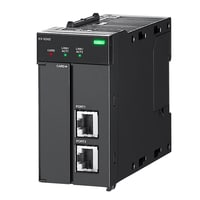
Database Communication Unit
|
Model |
KV-XCM02 |
|||
|
Image |
|
|||
|
General specifications |
Power voltage |
System configuration using a KV-5000/3000 Series expansion unit: 24 VDC (±10%) |
||
|
Operating ambient temperature |
System configuration using a KV-5000/3000 Series expansion unit: 0 to +50°C 32 to 122°F (No freezing) |
|||
|
Operating ambient humidity |
System configuration using a KV-5000/3000 Series expansion unit: 10 to 95% RH (No condensation) |
|||
|
Storage ambient temperature |
System configuration using a KV-5000/3000 Series expansion unit: −20 to +70°C -4 to +158°F |
|||
|
Storage relative humidity |
System configuration using a KV-5000/3000 Series expansion unit: 10 to 95% RH (No condensation) |
|||
|
Operating environment |
No dust or corrosive gas |
|||
|
Operating altitude |
2000 m 6561.7' or less |
|||
|
Noise immunity |
1500 Vp-p or more; Pulse duration: 1 μs, 50 ns (based on noise simulator); IEC standard-compliant (IEC 61000-4-2/3/4/6) |
|||
|
Withstand voltage |
1500 VAC for one minute (between the power terminals and the I/O terminals, and between the external terminals and the case) |
|||
|
Insulation resistance |
50 MΩ or more (between the power terminals and the I/O terminals and between the external terminals and the case, with 500 VDC megohmmeter) |
|||
|
Vibration resistance |
Intermittent vibration |
Frequency 5 to 9 Hz |
Half amplitude 3.5 mm 0.14"*4 |
|
|
Frequency 9 to 150 Hz |
Acceleration 9.8 m/s2 32.2'/s2*4 |
|||
|
Continuous vibration |
Frequency 5 to 9 Hz |
Half amplitude 1.75 mm 0.07"*4 |
||
|
Frequency 9 to 150 Hz |
Acceleration 4.9 m/s2 16.1'/s2*4 |
|||
|
Shock resistance |
Acceleration: 150 m/s2 492.1'/s2, Application time: 11 ms, 2 times in each of the X, Y, and Z directions |
|||
|
Pollution degree |
2 |
|||
|
Common specifications |
Connectable CPU unit |
KV-8000A/7500/7300 |
||
|
Max. number of connectable units |
14 |
|||
|
Connection interface |
RJ-45 8-position modular connector × 2 ports |
|||
|
Transmission rate |
10BASE-T: 10 Mbps |
|||
|
Transmission media |
10BASE-T: Category 3 or higher UTP or STP (STP is recommended) |
|||
|
Maximum cable length |
100 m 328.1'*7 |
|||
|
Maximum number of connectable hubs |
10BASE-T: 4 |
|||
|
Ethernet functions |
Socket communication, FTP server, FTP client, upper link communication, etc. |
|||
|
Internal current consumption |
200 mA or less |
|||
|
Weight |
Approx. 190 g 6.71 oz |
|||
|
Compatibility specifications |
Supported databases |
Microsoft SQL Server, PostgreSQL, MariaDB, MySQL, Oracle Database*9 |
||
|
Maximum number of connections |
4 |
|||
|
Supported SQL |
INSERT*10, UPDATE, SELECT*10, DELETE, TRUNCATE, Stored procedure/Stored function execution |
|||
|
Maximum number of supported columns |
1024 (Microsoft SQL Server); 1000 (PostgreSQL, MariaDB, MySQL, Oracle Database) |
|||
|
Maximum record storage size |
200000 bytes*11 |
|||
|
Buffer retransmission function |
Function that buffers SQL statements if communication fails to enable retransmission when communication is restored Maximum buffer capacity: 1 GB per connection (SD card required) |
|||
|
*1 Supplied via the CPU unit or expansion unit. |
||||

Information/Network unit
|
Model |
KV-XL202 |
KV-XL402 |
KV-XLE02 |
|||
|
Image |
|
|
|
|||
|
Type |
Serial communication unit |
Ethernet unit |
||||
|
Communication standard |
RS-232C |
RS-422A RS-485 (4 wires), RS-422A RS-485 (2 wires) |
||||
|
Connection interface |
European terminal block with 7 poles (detachable) × 2 ports |
European terminal block with 5 poles (detachable) × 2 ports |
RJ-45 8-pole modular connector × 2 ports |
|||
|
Transmission specifications |
Electrical termination (terminator) |
- |
ON/OFF set by the switch on the front face |
|||
|
Transmission rate |
1200, 2400, 4800, 9600, 19200, 38400, 57600, 115200, 230400 bps |
10BASE-T: 10 Mbps, 100BASE-TX: 100 Mbps, 1000BASE-T: 1000 Mbps |
||||
|
Transmission media |
10BASE-T: Category 3 or higher UTP or STP (STP is recommended) |
|||||
|
Transmission method |
Full duplex |
RS-422A RS-485 (4 wires): Full duplex |
||||
|
Data format |
Start bit: 1 bit |
|||||
|
Error detection |
Parity: Even, odd, none |
|||||
|
RS/CS flow control |
ON or OFF |
ON or OFF (only in PLC link mode) |
||||
|
Transmission distance |
15 m 49.2' |
Total extension: 1200 m 3937.0' max.*3*4 |
||||
|
Number of transmission units |
1 |
32*3 |
||||
|
Max. cable length |
10BASE-T: 100 m 328.1' |
|||||
|
Max. number of connectable hubs |
10BASE-T: 4 |
|||||
|
Refresh |
Automatic refresh, direct refresh, inter-unit synchronization refresh |
|||||
|
Ethernet functions |
KV socket communication, PLC link, PROTOCOL STUDIO, FTP server/client, KV sensor network, Modbus server*9, MC protocol/SLMP*10, etc. |
|||||
|
Industrial networks |
EtherNet/IP®, PROFINET, EtherCAT®,*11 CC-Link IE Field*12*13 |
|||||
|
Serial communication functions |
Non-procedure, PROTOCOL STUDIO, Modbus slave, etc. |
|||||
|
Ethernet function execution methods |
Ladder program, unit program (flow) |
|||||
|
Serial communication function execution methods |
Ladder program, unit program (flow) |
|||||
|
Unit program capacity |
3 MB (Max. number of blocks: Approx. 20000) |
|||||
|
flow |
Max. number of flows |
256 |
||||
|
Number of simultaneous activities |
Unlimited |
|||||
|
Flow |
Internal data Memory |
524288 words |
||||
|
PROTOCOL STUDIO |
Transmission method |
Cyclic communication: Tx + Rx, Tx only, Rx only |
Cyclic communication: Tx + Rx, Tx only, Rx only. |
|||
|
Max. number of connected devices |
2 |
16 |
||||
|
Max. number of communication commands |
48/96*1 |
160/320*14 |
||||
|
Maximum number of total frames |
Rx: 48/96*1 × 16; |
Rx: 160/320*14 × 16 Tx: 160/320*14 × 1 |
||||
|
Max. number of compared received frames |
16 per command |
|||||
|
Maximum number of block elements |
96 per frame |
|||||
|
Transmission data length |
1 to 2048 bytes per frame |
Standard: 1 to 2048 bytes per frame, |
||||
|
Reception data length |
||||||
|
PLC link |
Communication patterns |
Write, read, transfer |
||||
|
Number of link settings |
512 settings max.*2 |
512 settings max.*15 |
||||
|
Link data size |
1440 words max. per setting (bit: 720 words, word: 720 words) |
1440 words max. per setting (bit: 720 words, word: 720 words), |
||||
|
Data unit |
1 word |
|||||
|
Number of connected models |
2 models max. (1 model × 2 ports) |
16 models max.*15 |
||||
|
Number of connected units |
2 max. (1 unit × 2 ports) |
64 max.*15 |
||||
|
Trigger types |
Cyclic/event (64 settings max. for event*2) |
Cyclic/event (64 settings max. for event*15) |
||||
|
Update interval |
10 to 65535 ms |
1 to 65535 ms |
||||
|
Internal current consumption |
140 mA or less |
150 mA or less |
200 mA or less |
|||
|
Weight |
Approx. 200 g |
Approx. 190 g |
Approx. 190 g 6.71 oz |
|||
|
*1 The max. is 48 when “Standard” is set for the number of communication commands in Unit Editor and 96 when “Extended” is set. |
||||||


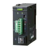
DeviceNet® Unit
|
Model |
KV-DN20 |
|||
|
Image |
|
|||
|
Type |
DeviceNet® unit |
|||
|
Communication protocol |
Compliant with DeviceNet® |
|||
|
Transmission specifications |
Transmission rate |
500 kbps, 250 kbps, 125 kbps |
||
|
Transmission media |
5 dedicated cables (2 for signal system, 2 for power supply, 1 for shield line) |
|||
|
Connection topology |
Multidrop method |
|||
|
Max. cable length |
Thick cable: 500 m 1640.4' (Transmission speed: 125 kbps), 250 m 820.2' (Transmission speed: 250 kbps), 100 m 328.1' (Transmission speed: 500 kbps) |
|||
|
Maximum number of connected nodes |
64 (including master, slave, configurator) |
|||
|
Master mode |
Connected pieces per network |
Max. 64 |
||
|
Type of communication |
I/O communication (Poll/Bit-Strobe/COS/Cyclic) Explicit message communication |
|||
|
Type and size of assigned devices |
Relay or data memory (indicated per block) max. size (per block) |
|||
|
Assignment method of device |
Auto configuration (Fixed or assigned with front end) and manual assignment |
|||
|
Slave connection pieces per unit |
Max. 63 |
|||
|
Maximum number of I/O per slave |
Input: 2048 points (128 words), Output: 2048 points (128 words) |
|||
|
Data length of message communication |
Sending: 106 bytes, Receiving: 110 bytes |
|||
|
Slave mode |
Connected pieces per network |
Max. 64 |
||
|
Type of communication |
I/O communication (Poll) Explicit message communication |
|||
|
Type and size of assigned devices |
Relaying or data memory, Max. size for relay: Input 64 ch, Output 64 ch; For data memory: Input 128 words, Output 128 words |
|||
|
Internal current consumption |
Internal circuit: 24 VDC, 45 mA or less (supplied by CPU unit), Communication circuit: 24 VDC 25 mA or less (supplied by communication connector) |
|||
|
Weight |
Approx. 150 g |
|||
Camera input unit
|
Model |
KV-CA02*1 |
|||
|
Image |
|
|||
|
General specifications |
Power voltage |
System configuration using an expansion unit for KV-5000/3000 Series: 24 VDC (±10%)*2 |
||
|
Operating ambient temperature |
System configuration using an expansion unit for KV-5000/3000 Series: 0 to +50°C 32 to 122°F |
|||
|
Operating ambient humidity |
System configuration using an expansion unit for KV-5000/3000 Series: 10 to 95% RH |
|||
|
Storage ambient temperature |
System configuration using an expansion unit for KV-5000/3000 Series: -20 to +70°C -4 to +158°F*3 |
|||
|
Storage relative humidity |
System configuration using an expansion unit for KV-5000/3000 Series: 10 to 95% RH |
|||
|
Operating environment |
No dust or corrosive gas |
|||
|
Operating altitude |
2000 m 6561.7' or less |
|||
|
Noise immunity |
1500 Vp-p or more |
|||
|
Withstand voltage |
1500 VAC for one minute (between the power terminals and the I/O terminals, and between the external terminals and the case) |
|||
|
Insulation resistance |
50 MΩ or more (between the power terminals and the I/O terminals and between the external terminals and the case, with 500 VDC megohmmeter) |
|||
|
Vibration resistance |
Intermittent vibration |
Frequency 5 to 9 Hz |
Half amplitude 3.5 mm 0.14"*5 |
|
|
Frequency 9 to 150 Hz |
Acceleration 9.8 m/s2 32.2'/s2*5 |
|||
|
Continuous vibration |
Frequency 5 to 9 Hz |
Half amplitude 1.75 mm 0.07"*5 |
||
|
Frequency 9 to 150 Hz |
Acceleration 4.9 m/s2 16.1'/s2*5 |
|||
|
Shock resistance |
Acceleration: 150 m/s2 492.1'/s2, Application time: 11 ms, 2 times in each of the X, Y, and Z directions |
|||
|
Pollution degree |
2 |
|||
|
Performance specifications |
Connectable CPU unit |
KV-8000A |
||
|
Max. number of connectable units |
4 |
|||
|
Number of ports |
2 |
|||
|
Supported camera models |
KV-CA1H (Compact standard camera) |
|||
|
Cable length |
5/10/20 m 16.4'/32.8'/65.6'*6 |
|||
|
Recording time |
Approx. 3 minutes*7 |
|||
|
Internal current consumption |
260 mA or less*8 |
|||
|
Weight |
Approx. 190 g |
|||
|
*1 for use with KV-8000 Series |
||||

Camera
|
Model |
KV-CA1H |
KV-CAC1H |
KV-CA1W |
KV-CAC1R |
|||
|
Image |
|
|
|
|
|||
|
General specifications |
Vibration resistance |
10 to 500 Hz; Power spectral density: |
|||||
|
Operating ambient temperature |
0 to +50°C 32 to 122°F (No freezing) |
||||||
|
Operating ambient humidity |
35 to 85% RH (No condensation) |
||||||
|
Storage ambient temperature |
−20 to +60°C -4 to +140°F (No freezing) |
||||||
|
Storage relative humidity |
35 to 85% RH (No condensation) |
||||||
|
Enclosure rating |
IP65F*1*2 |
IP64*4 |
IP65F*1*2 |
IP64*4 |
|||
|
Pollution degree |
3 |
||||||
|
Performance specifications |
Installation distance |
200 mm 7.87" to ∞ |
Varies by lens |
100 mm 3.94" to ∞ |
Varies by lens |
||
|
Focal distance |
3.8 mm 0.15" (fixed) |
1.05 mm 0.04" (fixed) |
|||||
|
Field of view |
Horizontal field of view: Approx. 60° |
Horizontal field of view: Varies by lens |
Horizontal field of view: Approx. 180° |
Horizontal field of view: Varies by lens |
|||
|
Image-receiving element |
1/2.9-inch color CMOS |
||||||
|
Resolution |
640 (H) × 480 (V) |
1280 (H) × 960 (V) |
|||||
|
Frame rate |
10/30/120 fps |
10/30 fps |
|||||
|
Internal current consumption |
70 mA or less *3 |
||||||
|
Weight |
Approx. 90 g 3.18 oz |
Approx. 65 g 2.29 oz |
Approx. 140 g 4.94 oz |
Approx. 65 g 2.29 oz |
|||
|
*1 The enclosure rating is evaluated with the camera cable connected. |
|||||||


C-mount lens
|
Model |
KV-CAL03 |
KV-CAL06 |
KV-CAL16 |
KV-CAL50 |
|||
|
Image |
|
|
|
|
|||
|
Focal distance |
3.5 mm 0.14" |
6 mm 0.24" |
16 mm 0.63" |
50 mm 1.97" |
|||
|
F-stop |
F1.6 to CLOSE |
F1.4 to CLOSE |
F1.6 to CLOSE |
F1.8 to CLOSE |
|||
|
Minimum working distance |
0.1 m 0.3' |
0.2 m 0.7' |
0.4 m 1.3' |
1.0 m 3.3' |
|||
|
Supported cameras |
KV-CAC1H/KV-CAC1R |
||||||


Power unit
|
Model |
KV-PU1 |
|||
|
Image |
|
|||
|
Type |
AC power unit |
|||
|
Input supply voltage |
100 to 240 VAC (-15%/+10%) (50/60 Hz) |
|||
|
Output voltage |
24 VDC ±10% |
|||
|
Output capacity |
1.8 A (total power supply to various units and extra power supply) |
|||
|
Internal power consumption |
0.96 A or less |
|||
|
Momentary stop time |
20 ms or less (depending on rated I/O conditions) |
|||
|
Starting time |
Max. 3 sec. or less |
|||
|
Error output |
Output mode |
Relay (NC contact) |
||
|
Rated load |
24 VDC, 0.5 A |
|||
|
ON resistance |
50 mΩ or less |
|||
|
Response time |
OFF to ON: 10 ms or less, ON to OFF: 5 ms or less |
|||
|
Relay life |
Electrical: 100000 times or more (20 times/min.) Mechanical: 20 million times or more |
|||
|
Relay replacement |
Impossible |
|||
|
Weight |
Approx. 300 g |
|||

Remote I/O Expansion input unit
|
Model |
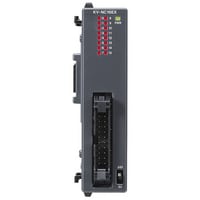
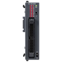
KV-NC16EX |
KV-NC16EXE |
KV-NC32EX |
|||
|
Image |
|
|
|
|||
|
Expansion input unit |
External connection method |
Connector |
European terminal block |
Connector |
||
|
Input Points |
16 points |
32 points |
||||
|
Input terminals |
24 VDC mode, 5 VDC mode |
|||||
|
Maximum input voltage |
26.4 VDC |
|||||
|
Input rated voltage |
24 VDC mode |
5.2 mA |
||||
|
5 VDC mode |
1 mA |
|||||
|
Minimum ON voltage |
24 VDC mode |
19 V |
||||
|
5 VDC mode |
3.5 V |
|||||
|
Maximum OFF current |
24 VDC mode |
1.5 mA |
||||
|
Maximum OFF voltage |
24 VDC mode |
1.5 V |
||||
|
Common method |
16 points/1 common (2 terminals) *1 |
16 points/1 common (16 terminals) *2 |
32 points/1 common (2 terminals) *1 |
|||
|
Input time constant (four-level switching) |
Input time constant setting |
OFF to ON: Typ. |
25 μs : 10 μs |
25 µs : 10 µs |
25 μs : 10 μs |
|
|
OFF to ON: Max. |
25 μs : 50 μs |
25 µs : 50 µs |
25 μs : 50 μs |
|||
|
ON to OFF: Typ. |
25 μs : 50 μs |
25 µs : 50 µs |
25 μs : 50 μs |
|||
|
ON to OFF: Max. |
25 μs : 150 μs |
25 µs : 150 µs |
25 μs : 150 μs |
|||
|
Input impedance |
4.4 kΩ |
|||||
|
Internal current consumption |
20 mA or less |
|||||
|
Weight |
Approx. 100 g |
Approx. 120 g |
Approx. 110 g |
|||
|
*1 The KV-NC16EX and KV-NC32EX have 2 COM terminals, but these are shared internally. |
||||||

Remote I/O Expansion input unit
|
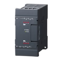
Model |
KV-N16EX |
KV-N8EX |
|||
|
Image |
|
|
|||
|
Expansion input unit |
External connection method |
Terminal block |
|||
|
Input terminals |
24 VDC mode,5 VDC mode |
||||
|
Maximum input voltage |
26.4 VDC |
||||
|
Input rated voltage |
24 VDC mode |
5.3 mA |
|||
|
5 VDC mode |
1 mA |
||||
|
Minimum ON voltage |
24 VDC mode |
19 V |
|||
|
5 VDC mode |
3.5 V |
||||
|
Maximum OFF current |
24 VDC mode |
1.5 mA |
|||
|
Maximum OFF voltage |
24 VDC mode |
1.5 V |
|||
|
Common method |
16 points/1 common (2 terminals) *1 |
8 points/1 common (2 terminals) *1 |
|||
|
Input time constant (four-level switching) |
Input time constant setting |
OFF to ON: Typ. |
25 μs : 10 μs |
||
|
OFF to ON: Max. |
25 μs : 50 μs |
||||
|
ON to OFF: Typ. |
25 μs : 50 μs |
||||
|
ON to OFF: Max. |
25 μs : 150 μs |
||||
|
Input impedance |
4.3 kΩ |
||||
|
Internal current consumption |
20 mA or less |
||||
|
Weight |
Approx. 220 g |
Approx. 150 g |
|||
|
*1 The KV-N8EX and KV-N16EX have 2 COM terminals, but these are shared internally. |
|||||

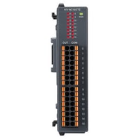
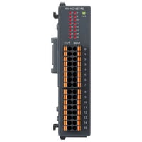
Remote I/O Expansion output unit
|
Model |
KV-NC16ETE |
KV-NC16ETPE |
KV-NC8ER |
|||
|
Image |
|
|
|
|||
|
Expansion output unit |
External connectionmethod |
MOSFET output (With overcurrent protection function)*1*2 |
Relay |
|||
|
External connection method |
European terminal block |
|||||
|
Rated load |
30 VDC, 0.2 A*3 |
250 VAC/30 VDC, 2 A |
||||
|
Leakage current (when output is OFF) |
100 μA or less |
− |
||||
|
Residual voltage (at ON) |
0.6 VDC or less |
|||||
|
ON resistance |
- |
50 mΩ or less |
||||
|
Common method |
16 points/1 common (16 terminals)*4 |
4 points/1 common (4 terminals) *5 |
||||
|
Response time |
OFF to ON |
100 μs or less (with a load of 1 mA or more) |
10 ms or less |
|||
|
ON to OFF |
200 μs or less (with a load of 1 mA or more) |
|||||
|
Relay life |
- |
Electrical: 100000 cycles or more (20 cycles/minute) |
||||
|
Relay replacement |
Impossible |
|||||
|
Internal current consumption |
30 mA or less |
70 mA or less |
||||
|
Weight |
Approx. 120 g |
Approx. 130 g |
||||
|
*1 If even a single overcurrent is detected, the protection operation (output turned OFF) and automatic recovery are repeated for all outputs within the shared common (The outputs within the shared common that are protected when an overcurrent is detected are outputs 000 to 007 or 008 to 015.), until the cause of the problem is removed. |
||||||

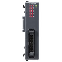
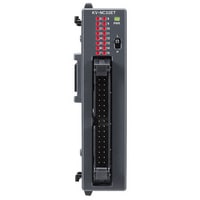
Remote I/O Expansion output unit
|
Model |
KV-NC16ET |
KV-NC16ETP |
KV-NC32ET |
KV-NC32ETP |
|||
|
Image |
|
|
|
|
|||
|
Expansion output unit |
External connectionmethod |
MOSFET (With overcurrent protection function)*1*2 |
MOSFET (With overcurrent protection function)*6*2 |
||||
|
External connection method |
Connector |
||||||
|
Rated load |
30 VDC. 0.2 A *3 |
||||||
|
Leakage current (when output is OFF) |
100 μA or less |
||||||
|
Residual voltage (at ON) |
0.6 VDC or less |
||||||
|
ON resistance |
− |
||||||
|
Common method |
16 points/1 common (2 terminals)*4*5 |
32 points/1 common (2 terminals)*4*7 |
|||||
|
Response time |
OFF to ON |
100 μs or less (with a load of 1 mA or more) |
|||||
|
ON to OFF |
200 μs or less (with a load of 1 mA or more) |
||||||
|
Relay life |
− |
||||||
|
Relay replacement |
|||||||
|
Internal current consumption |
30 mA or less |
50 mA or less |
|||||
|
Weight |
Approx. 100 g |
Approx. 110 g |
|||||
|
*1 If even a single overcurrent is detected, the protection operation (output turned OFF) and automatic recovery are repeated for all outputs within the shared common (The outputs within the shared common that are protected when an overcurrent is detected are outputs 000 to 007 or 008 to 015 for the KV-NC16ET(P) or KV-NC16ET(P)E.) , until the cause of the problem is removed. |
|||||||
Remote I/O Expansion output unit
|
Model |
KV-N16ER |
KV-N16ET |
KV-N16ETP |
|||
|
Image |
|
|
|
|||
|
Expansion output unit |
Output Points |
16 points |
||||
|
External connectionmethod |
Relay |
MOSFET |
||||
|
External connection method |
Terminal block |
|||||
|
Rated load |
250 VAC/30 VDC, 2 A |
30 VDC, 0.5 A |
||||
|
Leakage current (when output is OFF) |
− |
100 μA or less |
||||
|
Residual voltage (at ON) |
0.8 VDC or less (with 0.5 A output) |
|||||
|
ON resistance |
50 mΩ or less |
− |
||||
|
Common method |
4 points/1 common |
16 points/1 common |
||||
|
Response time |
OFF to ON |
10 ms or less |
100 μs or less (with a load of 1 mA or more) |
|||
|
ON to OFF |
200 μs or less (with a load of 1 mA or more) |
|||||
|
Relay life |
Electrical: 100000 cycles or more (20 cycles/minute) |
− |
||||
|
Relay replacement |
Impossible |
|||||
|
Internal current consumption |
100 mA or less |
40 mA or less |
||||
|
Weight |
Approx. 260 g |
Approx. 210 g |
||||
|
*1 The KV-N16ER has two terminals for each of C0, C1, C2, and C3 respectively, which are shorted internally. (C0, C1, C2, and C3 are independent.) |
||||||
Remote I/O Expansion output unit
|
Model |
KV-N8ER |
KV-N8ET |
KV-N8ETP |
|||
|
Image |
|
|
|
|||
|
Expansion output unit |
Output Points |
8 points |
||||
|
External connectionmethod |
Relay |
MOSFET |
||||
|
External connection method |
Terminal block |
|||||
|
Rated load |
250 VAC/30 VDC, 2 A |
30 VDC, 0.5 A |
||||
|
Leakage current (when output is OFF) |
− |
100 μA or less |
||||
|
Residual voltage (at ON) |
0.8 VDC or less (with 0.5 A output) |
|||||
|
ON resistance |
50 mΩ or less |
− |
||||
|
Common method |
Independent |
8 points/1 common |
||||
|
Response time |
OFF to ON |
10 ms or less |
100 μs or less (with a load of 1 mA or more) |
|||
|
ON to OFF |
200 μs or less (with a load of 1 mA or more) |
|||||
|
Relay life |
Electrical: 100000 cycles or more (20 cycles/minute) |
− |
||||
|
Relay replacement |
Impossible |
|||||
|
Internal current consumption |
60 mA or less |
30 mA or less |
||||
|
Weight |
Approx. 230 g |
Approx. 160 g |
||||
|
*1 If even a single overcurrent is detected, the protection operation (output turned OFF) and automatic recovery are repeated for all outputs within the shared common (The outputs within the shared common that are protected when an overcurrent is detected are outputs 000 to 007 or 008 to 015 for the case of the KV-N16ET(P).) , until the cause of the problem is removed. |
||||||
Remote I/O Expansion I/O unit
|
Model |
KV-NC16EXT |
KV-NC32EXT |
|||
|
Image |
|
|
|||
|
Expansion input unit |
External connection method |
Connector |
|||
|
Input Points |
16 |
32 |
|||
|
Input terminals |
24 VDC mode, 5 VDC mode |
24 VDC mode |
|||
|
Maximum input voltage |
26.4 VDC |
||||
|
Input rated voltage |
24 VDC mode |
5.2 mA |
3.6 mA |
||
|
5 VDC mode |
1 mA |
― |
|||
|
Minimum ON voltage |
24 VDC mode |
19 V |
|||
|
5 VDC mode |
3.5 V |
― |
|||
|
Maximum OFF current |
24 VDC mode |
1.5 mA |
|||
|
Maximum OFF voltage |
24 VDC mode |
1.5 V |
― |
||
|
Common method |
16 points/1 common (1 terminal)*1 |
32 points/1 common (2 terminals)*1 |
|||
|
Input time constant (four-level switching) |
Input time constant setting |
OFF to ON: Typ. |
25 μs : 10 μs |
||
|
OFF to ON: Max. |
25 μs : 50 μs |
||||
|
ON to OFF: Typ. |
25 μs : 50 μs |
||||
|
ON to OFF: Max. |
25 μs : 150 μs |
||||
|
Input impedance |
4.4 kΩ |
6.3 kΩ |
|||
|
Expansion output unit |
Output Points |
16 |
32 |
||
|
External connectionmethod |
MOSFET (N-ch) |
||||
|
External connection method |
Connector |
||||
|
Rated load |
30 VDC 0.2 A *3 |
||||
|
Leakage current (when output is OFF) |
100 μA or less |
||||
|
Residual voltage (at ON) |
0.6 VDC or less |
||||
|
Common method |
16 points/1 common (1 terminal) *1 |
32 points/1 common (2 terminals) *1 |
|||
|
Response time |
OFF to ON |
100 μs or less (with a load of 1 mA or more) |
|||
|
ON to OFF |
200 μs or less (with a load of 1 mA or more) |
||||
|
Internal current consumption |
30 mA or less |
60 mA or less |
|||
|
Weight |
Approx. 120 g |
Approx. 150 g |
|||
|
*1 The input COM and output COM terminals are independent. |
|||||

Remote I/O Expansion I/O unit
|
Model |
KV-N8EXR |
KV-N8EXT |
|||
|
Image |
|
|
|||
|
Expansion input unit |
External connection method |
Terminal block |
|||
|
Input Points |
8 |
||||
|
Input terminals |
24 VDC mode, 5 VDC mode |
||||
|
Maximum input voltage |
26.4 VDC |
||||
|
Input rated voltage |
24 VDC mode |
5.3 mA |
|||
|
5 VDC mode |
1 mA |
||||
|
Minimum ON voltage |
24 VDC mode |
19 V |
|||
|
5 VDC mode |
3.5 V |
||||
|
Maximum OFF current |
24 VDC mode |
1.5 mA |
|||
|
Maximum OFF voltage |
24 VDC mode |
1.5 V |
|||
|
Common method |
8 points/1 common (1 terminal) *1 |
||||
|
Input time constant (four-level switching) |
Input time constant setting |
OFF to ON: Typ. |
25 μs : 10 μs |
||
|
OFF to ON: Max. |
25 μs : 50 μs |
||||
|
ON to OFF: Typ. |
25 μs : 50 μs |
||||
|
ON to OFF: Max. |
25 μs : 150 μs |
||||
|
Input impedance |
4.3 kΩ |
||||
|
Expansion output unit |
Output Points |
8 |
|||
|
External connectionmethod |
Relay |
MOSFET (N-ch) |
|||
|
Rated load |
250 VAC/30 VDC, 2 A |
30 VDC, 0.5 A |
|||
|
Leakage current (when output is OFF) |
− |
100 μA or less |
|||
|
Residual voltage (at ON) |
0.8 VDC or less (with 0.5 A output), 0.6 VDC or less (with 0.3 A output) |
||||
|
ON resistance |
50 mΩ or less |
− |
|||
|
Common method |
4 points/1 common (2 terminals) *1*2 |
8 points/1 common (4 terminals) *1*4 |
|||
|
Response time |
OFF to ON |
10 ms or less |
100 μs or less (with a load of 1 mA or more) |
||
|
ON to OFF |
200 μs or less (with a load of 1 mA or more) |
||||
|
Relay life |
Electrical: 100000 cycles or more (20 cycles/minute) |
− |
|||
|
Relay replacement |
Impossible |
||||
|
Internal current consumption |
60 mA or less |
30 mA or less |
|||
|
Weight |
Approx. 230 g |
Approx. 210 g |
|||
|
*1 The input COM and output COM terminals are independent. |
|||||
Analog unit
|
Model |
KV-N3AM |
KV-NC2DA |
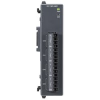
KV-NC4AD |
|||
|
Image |
|
|
|
|||
|
Conversion speed |
80 μs/channel *1 |
80 μs/channel |
80 μs/channel*1 |
|||
|
Conversion |
A/D conversion, D/A conversion |
D/A conversion |
A/D conversion |
|||
|
Points |
A/D conversion : 2 (single end), D/A conversion : 1 |
2 |
4 (single end) |
|||
|
Range/resolution |
Voltage |
-10 V to +10 V |
A/D conversion : 1/8000 2.5 mV, D/A conversion : 1/8000 2.5 mV *2 |
1/8000 2.5 mV |
||
|
0 to 10 V |
A/D conversion : 1/4000 2.5 mV, D/A conversion : 1/4000 2.5 mV *2 |
1/4000 2.5 mV |
||||
|
0 to 5 V |
A/D conversion : 1/4000 1.25 mV, D/A conversion : 1/4000 1.25 mV *2 |
1/4000 1.25 mV |
||||
|
1 to 5 V |
A/D conversion : 1/3200 1.25 mV, D/A conversion : 1/3200 1.25 mV *2 |
1/3200 1.25 mV |
||||
|
Current |
0 to 20 mA |
A/D conversion : 1/4000 5 μA, D/A conversion : 1/4000 5 μA *2 |
1/4000 5 μA |
|||
|
4 to 20 mA |
A/D conversion : 1/3200 5 μA, D/A conversion : 1/3200 5 μA *2 |
1/3200 5 μA |
||||
|
Conversion precision |
Voltage |
Without temperature |
A/D conversion : |
±0.3% of F.S. (at 25°C ±5°C 77°F ±9°F) |
||
|
With temperature |
A/D conversion : |
±0.3% of F.S. (at 25°C ±5°C 77°F ±9°F) |
±0.3% of F.S. (at 0 to 55°C 32 to 131°F) |
|||
|
Current |
Without temperature |
A/D conversion : |
±0.4% of F.S. (at 25°C ±5°C 77°F ±9°F) |
|||
|
With temperature |
A/D conversion : |
±0.4% of F.S. (at 0 to 55°C 32 to 131°F) |
||||
|
Input resistance |
Voltage |
A/D conversion : 5 MΩ |
− |
5 MΩ |
||
|
Current |
A/D conversion : 250 Ω |
250 Ω |
||||
|
Absolute maximum input |
Voltage |
A/D conversion : ±15 V |
±15 V |
|||
|
Current |
A/D conversion : ±30 mA |
±30 mA |
||||
|
Isolation method |
Between analog input |
Isolated (photocoupler, transformer) |
||||
|
A/D , D/A conversion unit |
Isolation method |
Between Analog input - output |
Non-isolated |
|||
|
Isolation method |
Between analogu input channels |
A/D conversion : Non-isolated |
No isolation |
|||
|
Minimum load resistance |
Voltage |
D/A conversion : 1 kΩ |
1 kΩ |
− |
||
|
Maximum load resistance |
Current |
D/A conversion : 600 Ω |
600 Ω |
|||
|
Special functions |
▼A/D conversion |
output range switching, output data offset, scaling, |
Input range switching, |
|||
|
Internal current consumption |
120 mA or less |
|||||
|
Weight |
200 g |
|||||
|
*1 When the temperature fluctuation compensation is used, the temperature fluctuation compensation time of 80 μs will be added regardless of the number of channels being used. |
||||||

Temperature input unit
|
Model |
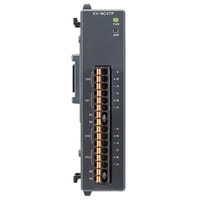
KV-NC4TP |
|||
|
Image |
|
|||
|
Temperature input unit |
Number of inputs |
4 *1 |
||
|
Input |
Thermocouple, Platinum resistance thermometer |
|||
|
Input range |
Thermocouple |
K: -270.0 to 1372.0°C -454 to 2501.6°F |
||
|
Platinum resistance thermometer |
Pt100: -200.0 to 850.0°C -328 to 1562°F |
|||
|
Overall accuracy |
Thermocouple |
±(0.2% of F.S. +1°C 1.8°F) (at 25°C ±5°C 77°F ±9°F) |
||
|
Platinum resistance thermometer |
±0.2% of F.S. (at 25°C ±5°C 77°F ±9°F) |
|||
|
Allowable wiring resistance |
Platinum resistance thermometer |
100 Ω max./wire |
||
|
Conversion speed |
125 ms/channel |
|||
|
Isolation method |
Between input terminals and base unit: |
|||
|
Special function |
Channel skip, disconnection detection, |
|||
|
Internal current consumption |
40 mA or less |
|||
|
Weight |
Approx. 110 g |
|||
|
*1 Individual setting is possible for each channel. |
||||
Connection conversion unit
|
Model |
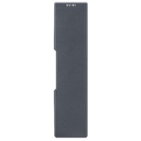
KV-N1 |
KV-NC1 |
|||
|
Image |
|
|
|||
|
Type |
Connection conversion unit For connector type unit connection |
Connection conversion unit For terminal block type unit connection |
|||
|
Note |
For connecting connector type expansion units |
For connecting terminal block type expansion units |
|||
|
Weight |
90 g |
80 g |
|||

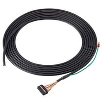
Harness cable, 20/34 electrode
|
Model |
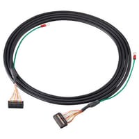
XC-H20-01 |
XC-H20-03 |
XC-H20-05 |
XC-H20D-05 |
XC-H34-01 |
XC-H34-03 |
XC-H34-05 |
XC-H34D-05 |
|||
|
Image |
|
|
|
|
|
|
|
|
|||
|
Rated voltage |
30 VDC |
||||||||||
|
Rated current |
1 A/pin |
||||||||||
|
Ambient operating temperature |
0 to +80°C |
||||||||||
|
Environmental resistance |
Insulation resistance |
500 VDC, 10 MΩ or greater |
|||||||||
|
Withstand voltage |
500 VAC, 1 minute, 1 mA or less |
||||||||||


Harness cable, 40 electrode
|
Model |
XC-H40-01 |
XC-H40-03 |
XC-H40-05 |
XC-H40D-05 |
|||
|
Image |
|
|
|
|
|||
|
Rated voltage |
30 VDC |
||||||
|
Rated current |
1 A/pin |
||||||
|
Ambient operating temperature |
0 to +80°C |
||||||
|
Environmental resistance |
Insulation resistance |
500 VDC, 10 MΩ or greater |
|||||
|
Withstand voltage |
500 VAC, 1 minute, 1 mA or less |
||||||


Converter terminal block, 20/26 electrode
|
Model |
XC-T20B1 |
XC-T20B2 |
XC-T20E1 |
XC-T20P |
XC-T26B |
XC-T26E |
|||
|
Image |
|
|
|
|
|
|
|||
|
Rated voltage |
125 VAC/DC |
||||||||
|
Rated current |
1 A/pin |
10 A/pin |
1 A/pin |
||||||
|
Ambient operating temperature |
−40 to +80°C |
||||||||
|
Screw torque |
0.8 N·m (max.) |
0.5 N·m (max.) |
0.8 N·m (max.) |
0.5 N·m (max.) |
|||||
|
Applicable wire diameter |
AWG22 to 16 |
AWG24 to 12 |
AWG22 to 16 |
AWG24 to 12 |
|||||
|
Environmental resistance |
Insulation resistance |
500 VDC, 1000 MΩ or greater |
500 VDC, 500 MΩ or greater |
500 VDC, 1000 MΩ or greater |
500 VDC, 500 MΩ or greater |
||||
|
Withstand voltage |
500 VAC, 1 minute, 1 mA or less |
2000 VAC, 1 minute, 1 mA or less |
500 VAC, 1 minute, 1 mA or less |
||||||
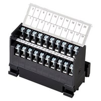


Converter terminal block, 34/40 electrode
|
Model |
XC-T34B1 |
XC-T34B2 |
XC-T34E1 |
XC-T34E2 |
XC-T40B1 |
XC-T40B2 |
XC-T40E1 |
XC-T40E2 |
XC-T40P |
|||
|
Image |
|
|
|
|
|
|
|
|
|
|||
|
Rated voltage |
125 VAC/DC |
|||||||||||
|
Rated current |
1 A/pin |
10 A/pin |
||||||||||
|
Ambient operating temperature |
−40 to +80°C |
|||||||||||
|
Screw torque |
0.8 N·m (max.) |
0.5 N·m (max.) |
0.8 N·m (max.) |
0.5 N·m (max.) |
0.8 N·m (max.) |
|||||||
|
Applicable wire diameter |
AWG22 to 16 |
AWG24 to 12 |
AWG22 to 16 |
AWG24 to 12 |
AWG22 to 16 |
|||||||
|
Environmental resistance |
Insulation resistance |
500 VDC, 1000 MΩ or greater |
500 VDC, 500 MΩ or greater |
500 VDC, 1000 MΩ or greater |
500 VDC, 500 MΩ or greater |
500 VDC, 1000 MΩ or greater |
||||||
|
Withstand voltage |
500 VAC, 1 minute, 1 mA or less |
2000 VAC, 1 minute, 1 mA or less |
||||||||||


Memory card
|
Model |
KV-M16G |
KV-M1G |
KV-M4G |
|||
|
Image |
|
|
|
|||
|
Type |
SD memory card |
SD Memory Card |
||||
|
Memory elements |
Flash ROM |
|||||
|
Type |
SDHC |
SDHC |
||||
|
Memory capacity |
16GB |
1 GB |
4GB |
|||
|
Number of rewrites |
60,000 operations (each block) |
100,000 times (per block) |
60,000 operations (each block) |
|||
|
Storage temperature |
-40 to +85°C |
-40 to +85°C -40 to 185°F |
-40 to +85°C |
|||
|
Operating temperature |
-25 to +85°C |
-25 to +85°C -13 to 185°F |
-25 to +85°C |
|||