Multi-input Data Logger
NR-X series
Specs Multi-input Data Logger NR-X series
Master data collection unit
|
Model |
NR-X100W |
|||
|
Image |
|
|||
|
Main unit buffer memory capacity |
50M data*1 |
|||
|
Expansion memory |
SD card (SD/SDHC)*2 |
|||
|
PC interface |
USB |
USB mini-B connector, USB 2.0 High-speed–compliant, Simultaneous USB connection from one PC to up to four units (switchable by ID switch) |
||
|
Ethernet |
RJ45 connector, 100Base-TX (AUTO MDI/MDIX supported) *3 |
|||
|
Wireless LAN |
Connection via NR-XW1 wireless LAN unit, IEEE 802.11b/g/n *3 |
|||
|
Network function |
FTP client function, FTP server function, SNTP client function |
|||
|
Display/operation |
Operation via NR-XCP30 control panel, or via WAVE LOGGER X with PC connection |
|||
|
Expansion remote unit connection |
Dedicated remote connection connector × 2 (Remote OUT A port, B port) |
|||
|
Number of connectable measurement units |
Master data collection unit group |
Max. 8 units*4 |
||
|
Total with remote units connected |
Max. 72 units*5 |
|||
|
Continuous acquisition speed |
Master data collection unit group |
Max. 100 kHz for all acquisition channels *6 |
||
|
Total with remote units connected |
Max. 500 kHz for all acquisition channels *6*7 |
|||
|
Inter-unit synchronization |
Between measurement units in the master data collection unit group |
±1 μs or less *8 |
||
|
Between the master data collection unit and each remote unit / environment-resistant measurement unit |
||||
|
Time axis accuracy |
±50 ppm (23°C ±3°C 73.4°F ±5.4°F); Same time used for all remote groups, SNTP server time synchronization possible |
|||
|
Synchronous trigger input (SYNC input) |
Performance specifications |
• Use as external trigger input (normal mode) or synchronous acquisition input (logging mode) |
||
|
Input specifications |
• For non-voltage input: ON voltage 1.0 V or lower (short circuit current: 1 mA typ.), OFF current 0.1 mA or lower |
|||
|
Control input |
Common specifications |
• Input type: Bidirectional voltage input |
||
|
Individual specifications |
• External trigger input (TRG IN): Edge input |
|||
|
Control output |
Common specifications |
• Output format: Photo MOS relay output |
||
|
Individual specifications |
• Trigger output (TRG OUT): N.O. output, one-shot output |
|||
|
Power supply |
• NR-XU1 AC adapter, or 9 to 36 VDC (including ripple) / Max. 72 W (when connected to DC terminal block; at 9 V: 8.0 A or less; at 24 V: 3.0 A or less; at 36 V: 2.0 A or less) |
|||
|
Power supply |
Power consumption |
8.4 W or less (excluding connected units) |
||
|
Environmental resistance |
Ambient temperature |
0 to +40°C 32°F to 104°F |
||
|
Relative humidity |
10 to 85% RH (no condensation) |
|||
|
Weight |
Approx. 490 g 17.30 oz (including approx. 10 g 0.35 oz for the OP-88512 (NR-X100W I/O terminal block)) |
|||
|
*1 Data is not backed up when the power is turned off. The available data buffer memory per NR-X100W and NR-XR01 group is limited to 25M. |
||||

Remote unit for NR-X
|
Model |
NR-XR01 |
|||
|
Image |
|
|||
|
Expansion remote connection |
Dedicated remote input port × 1 (Remote IN), Output port × 1 (Remote OUT) |
|||
|
Number of connectable measurement units |
Max. 8 units*2 |
|||
|
Continuous acquisition speed |
Max. 100 kHz for all acquisition channels*3 |
|||
|
Synchronization between measurement units |
±1 μs or less*4 |
|||
|
Power supply |
Supplied from NR-U5 AC adapter or NR-X100W master data collection unit (operation with no AC adapter) |
|||
|
Power supply |
Power consumption |
Approx. 2.9 W |
||
|
Environmental resistance |
Ambient temperature |
0 to +40°C 32°F to 104°F |
||
|
Relative humidity |
10 to 85% RH (no condensation) |
|||
|
Weight |
Approx. 210 g 7.41 oz |
|||
|
*1 Remote unit cables can be extended by connecting a remote extension cable. The total length of remote cables used in the system should be no more than 100 m 328.1'. The distance between the master data collection unit and remote units or between remote units should be no more than 60 m 196.9'. |
||||

High-accuracy temperature/voltage measurement unit
|
Model |
NR-TH08 *1 |
|||
|
Image |
|
|||
|
Type |
High-accuracy temperature/voltage measurement unit |
|||
|
Input method |
Floating unbalanced input, channels insulated from each other, CH inputs insulated from other units (PC), |
|||
|
Number of channels |
Input: 8 *2 |
|||
|
Measurement cycle |
Fastest sampling cycle: 100 ms (A/D integration time: 2 ms) to 1 h |
|||
|
A/D converting system |
Delta-sigma method |
|||
|
A/D resolution |
24 bit |
|||
|
A/D integration time |
2 ms, 16.7 ms, 20 ms |
|||
|
Input type |
Voltage: ±50 V, ±10 V, ±5 V, ±1 V, ±0.5 V, ±0.1 V; Thermocouple; K, J, E, T, R, S, B, N, C; |
|||
|
Measurement range |
±50 V |
Measurable range: −55.00 to +55.00 V |
||
|
±10 V |
Measurable range: −11.000 to +11.000 V |
|||
|
±5 V |
Measurable range: −5.500 to +5.500 V |
|||
|
±1 V |
Measurable range: −1.1000 to +1.1000 V |
|||
|
±500 mV |
Measurable range: −550.0 to +550.0 mV |
|||
|
±100 mV |
Measurable range: −110.00 to +110.00 mV |
|||
|
K |
Measurable range: −100 to +1372°C -148°F to +2501.6°F, −200 to −100°C -328°F to -148°F |
|||
|
J |
Measurable range: −100 to +1200°C -148°F to +2192°F, −200 to −100°C -328°F to -148°F |
|||
|
E |
Measurable range: −100 to +1000°C -148°F to +1832°F, −200 to −100°C -328°F to -148°F |
|||
|
T |
Measurable range: −100 to +400°C -148°F to +752°F, −200 to −100°C -328°F to -148°F |
|||
|
N |
Measurable range: 0 to 1300°C 32°F to 2372°F |
|||
|
C |
Measurable range: 1500 to 2315°C 2732°F to 4199°F, 0 to 1500°C 32°F to 2732°F |
|||
|
R |
Measurable range: 300 to 1768°C 572°F to 3214.4°F, 0 to 300°C 32°F to 572°F |
|||
|
S |
Measurable range: 300 to 1768°C 572°F to 3214.4°F, 0 to 300°C 32°F to 572°F |
|||
|
B |
Measurable range: 400 to 600°C 752°F to 1112°F, 600 to 1820°C 1112°F to 3308°F |
|||
|
Pt100 |
Measurable range: −200 to +660°C -328°F to +1220°F |
|||
|
JPt100 |
Measurable range: −200 to +510°C -328°F to +950°F |
|||
|
Reference contact compensation |
Switchable between internal and external (individual unit setting, 0°C 32°F for external) |
|||
|
Reference contact compensation accuracy |
±0.7°C ±1.3°F (23°C ±2°C 73.4°F ±3.6°F, at input terminal temperature equilibrium) |
|||
|
Maximum input voltage |
±60 V (rated) |
|||
|
Input impedance |
Thermocouple, Voltage: 5 V range or lower |
10 MΩ or more |
||
|
Voltage: 50 V, 10 V range |
Approx. 1 MΩ |
|||
|
Withstand voltage |
Measurement input terminal - System bus |
1500 VAC (50/60 Hz) for 1 minute |
||
|
Mutually between measurement input terminals |
120 Vp-p AC/DC |
|||
|
Input signal source resistance |
Voltage/thermocouple |
2 kΩ or less |
||
|
Resistance thermometer |
10 Ω or less per line (three lines must be equal) |
|||
|
Thermocouple burnout |
Wire breakage detected in the thermocouple range by applying 1 μA of current |
|||
|
Burnout detection frequency |
Detected in the measurement cycle |
|||
|
Buffer memory |
200k data |
|||
|
Warm up time |
30 minutes or more*5 |
|||
|
Rating |
Power consumption |
1.2 W or less |
||
|
Environmental resistance |
Ambient temperature |
0 to +40°C 32°F to 104°F |
||
|
Relative humidity |
10 to 85% RH (no condensation) |
|||
|
Weight |
Approx. 230 g 8.12 oz (including approx. 100 g 3.53 oz for the OP-51582 (NR-TH08 terminal block)) |
|||
|
*1 The above specifications are the values when zero point adjustment is performed after the warm-up period in an environment with a temperature of 23°C ±3°C 73.4°F ±5.4°F. |
||||

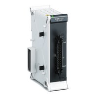
High-speed analog measurement unit
|
Model |
NR-HA08 *1 |
|||
|
Image |
|
|||
|
Type |
High-speed analog measurement unit |
|||
|
Input method |
Single-ended input / Balanced differential input selection |
|||
|
Number of channels |
Single-end: 8 ch*2 (Differential: 4 ch) / Current: 4 ch*3 |
|||
|
Measurement cycle |
Maximum sampling cycle: 1 μs (1 MHz) to 60 s |
|||
|
A/D converting system |
Successive approximation |
|||
|
A/D resolution |
14 bit |
|||
|
Input frequency band |
250 kHz (−3 dB typ.) |
|||
|
Input impedance |
Voltage |
1 MΩ ±1% |
||
|
Current |
250 Ω ±1% |
|||
|
Withstand voltage |
Input to system bus |
300 VAC (50/60 Hz), 1 minute |
||
|
Input type |
Voltage |
±10 V, ±5 V, ±2.5 V, ±1 V, ±0.5 V, ±0.25 V |
||
|
Current |
±20 mA |
|||
|
Maximum input rating |
Voltage range |
±30 V |
||
|
Current range |
±30 mA |
|||
|
Measurable range |
±10 V: −11.000 to +11.000 V |
|||
|
Measurement accuracy |
Zero-point accuracy |
±0.03% of F.S. |
||
|
DC amplitude accuracy |
±0.1% of F.S. (10 V/5 V/2.5 V/20 mA range at 16 averages, 1 V/0.5 V/0.25 V range at 128 averages) |
|||
|
Display resolution |
±10 V: 1 mV |
|||
|
Buffer memory |
4M data*4 |
|||
|
Warm up time |
15 minutes or more |
|||
|
Rating |
Power consumption |
3.3 W or less |
||
|
Environmental resistance |
Ambient temperature |
0 to +40°C 32°F to 104°F |
||
|
Relative humidity |
10 to 85% RH (no condensation) |
|||
|
Weight |
Approx. 150 g 5.30 oz |
|||
|
*1 The above specifications are the values when zero point adjustment is performed after the warm-up period in an environment with a temperature of 23°C ±3°C 73.4°F ±5.4°F. |
||||
High-accuracy temperature measurement unit (Thermocouple connectors)
|
Model |
NR-TH08P *1 |
|||
|
Image |
|
|||
|
Input method |
Floating unbalanced input, channels insulated from each other, inputs insulated from other units (PC) |
|||
|
Number of channels |
Input: 8 *2 |
|||
|
Measurement cycle |
Fastest sampling cycle of 100 ms (A/D integration time: 2 ms) to 1 h |
|||
|
A/D converting system |
Delta-sigma method |
|||
|
A/D resolution |
24 bit |
|||
|
A/D integration time |
2 ms, 16.7 ms, 20 ms |
|||
|
Input type |
Thermocouple: K, J, E, T, R, S, B, N, C |
|||
|
Reference contact compensation |
Switchable between internal and external (individual unit setting, 0°C 32°F for external) |
|||
|
Reference contact compensation accuracy |
±0.5°C ±0.9°F (23°C ±3°C 73.4°F ±5.4°F, at input terminal temperature equilibrium) |
|||
|
Maximum input voltage |
±60 V (rated) |
|||
|
Input impedance |
10 MΩ or more |
|||
|
Withstand voltage |
Measurement input terminal - System bus |
1500 VAC (50/60 Hz) for 1 minute |
||
|
Mutually between measurement input terminals |
120 Vp-p AC/DC |
|||
|
Input connector |
Miniature thermocouple connector (Universal Cu/Cu type) × 8 ports |
|||
|
Input signal source resistance |
2 kΩ or less |
|||
|
Thermocouple burnout |
Wire breakage detected by applying 1 μA of current |
|||
|
Burnout detection frequency |
Detected in the measurement cycle |
|||
|
Measurable range |
K: −100 to +1372°C -148°F to +2501.6°F, −200 to −100°C -328°F to -148°F *3 |
|||
|
Measurement accuracy (A/D integration time: 16.7 ms, 20 ms) |
K: ±0.05% of rdg ±0.6°C ±1.1°F, ±0.05% of rdg ±0.9°C ±1.6°F *3 |
|||
|
Display resolution |
K: 0.05°C 0.09°F *3 |
|||
|
Buffer memory |
200k data |
|||
|
Warm up time |
30 minutes or more*4 |
|||
|
Power supply |
Power consumption |
1.2 W or less |
||
|
Environmental resistance |
Ambient temperature |
0 to +40°C 32°F to 104°F |
||
|
Relative humidity |
10 to 85% RH (no condensation) |
|||
|
Weight |
Approx. 250 g 8.83 oz (including approx. 120 g 4.24 oz for the OP-88519 (NR-TH08P thermocouple connector terminal block)) |
|||
|
*1 The above specifications are the values when zero point adjustment is performed after the warm-up period in an environment with a temperature of 23°C ±3°C 73.4°F ±5.4°F. |
||||

High-speed analog measurement unit (Push-type terminal block)
|
Model |
NR-HA08P *1 |
|||
|
Image |
|
|||
|
Input method |
Single-end input / Balanced differential input selection |
|||
|
Number of channels |
Single-end: 8 ch*2 (Differential: 4 ch) / Current: 4 ch |
|||
|
Measurement cycle |
Maximum sampling cycle: 1 μs (1 MHz) to 60 s |
|||
|
A/D converting system |
Successive approximation |
|||
|
A/D resolution |
14 bit |
|||
|
Input frequency band |
250 kHz (−3 dB typ.) |
|||
|
Input impedance |
Voltage |
1 MΩ ±1% |
||
|
Current |
250 Ω ±1% |
|||
|
Input type |
Voltage |
±10 V, ±5 V, ±2.5 V, ±1 V, ±0.5 V, ±0.25 V |
||
|
Current |
±20 mA |
|||
|
Maximum input rating |
Voltage range |
±30 V |
||
|
Current range |
±30 mA |
|||
|
Withstand voltage |
Between measurement input terminal and system bus |
300 VAC (50/60 Hz), 1 minute |
||
|
Measurable range |
±10 V: −11.000 to +11.000 V |
|||
|
Measurement accuracy |
Zero-point accuracy |
±0.03% of F.S. |
||
|
DC amplitude accuracy |
±0.1% of F.S. (10 V/5 V/2.5 V/20 mA range at 16 averages, 1 V/0.5 V/0.25 V range at 128 averages) |
|||
|
Display resolution |
±10 V: 1 mV |
|||
|
Buffer memory |
4M data*4 |
|||
|
Warm up time |
15 minutes or more |
|||
|
Power supply |
Power consumption |
3.3 W or less |
||
|
Environmental resistance |
Ambient temperature |
0 to +40°C 32°F to 104°F |
||
|
Relative humidity |
10 to 85% RH (no condensation) |
|||
|
Weight |
Approx. 170 g 6.00 oz (including approx. 20 g 0.71 oz for the OP-88521 (NR-HA08P terminal block)) |
|||
|
*1 The above specifications are the values when zero point adjustment is performed after the warm-up period in an environment with a temperature of 23°C ±3°C 73.4°F ±5.4°F. |
||||

High-speed, high-voltage measurement unit
|
Model |
NR-HV04 *1 |
|||
|
Image |
|
|||
|
Type |
High-speed, high-voltage measurement unit |
|||
|
Input method |
Insulated single-end input, channels insulated from each other, input channels insulated from other units (PC) |
|||
|
Number of channels |
4 ch *2 |
|||
|
Measurement cycle |
Maximum sampling cycle: 1 μs (1 MHz) to 60 s |
|||
|
A/D converting system |
Successive approximation, simultaneous sampling of all channels |
|||
|
A/D resolution |
14 bit |
|||
|
Input frequency band |
250 kHz (−3 dB or more) |
|||
|
Input type |
±1000 V, ±500 V, ±200 V, ±100 V, ±50 V, ±20 V, ±10 V, ±5 V, ±2 V |
|||
|
Low pass filter |
PASS, 7 Hz, 500 Hz, 50 kHz (−12 dB/oct) |
|||
|
Maximum input voltage |
[When using OP-35409 1:1 voltage-resistant probe] 1000 V peak and 700 Vrms, or 700 VDC; |
|||
|
Digital filter |
Averaging rate: 1 to 128 (automatically selected) |
|||
|
Withstand voltage |
Input to system bus/earth |
2200 VAC (50/60 Hz) for 1 minute |
||
|
Connector format |
Insulated BNC connector |
|||
|
Input impedance |
1 MΩ ±1%, approx. 30 pF |
|||
|
Input coupling |
AC/DC/AC-RMS/DC-RMS |
|||
|
Measurable range |
±1000 V: −1000.00 to +1000.00 V |
|||
|
Measurement accuracy |
±0.1% of F.S. |
|||
|
Display resolution |
±1000 V: 50 mV |
|||
|
Buffer memory |
16M data*4 |
|||
|
Warm up time |
30 minutes or more |
|||
|
RMS measurement function |
Number of channels |
4 ch |
||
|
Maximum allowable voltage to ground |
[When using OP-35409 1:1 voltage-resistant probe] Measurement terminal, GND terminal: 300 Vrms (CAT II); |
|||
|
RMS measurement function |
Accuracy |
Sine wave: 20 Hz to 1 kHz, ±0.5% of F.S.; 1 to 20 kHz, ±1.5% of F.S.; Crest factor: 4 or less; Response time: 500 ms |
||
|
Residual noise level |
0.01% of F.S., LPF: 500 Hz (200 μs/S, digital filter: ON) (typ.); 0.05% of F.S., LPF: PASS (typ.) |
|||
|
Calculationfunction |
CH1 to CH2, CH3 to CH4 (Single-channel usage not possible when using the calculation function) |
|||
|
Common mode noise reduction ratio |
80 dB or more (at max. 60 Hz DC) (typ.) |
|||
|
Rating |
Power consumption |
3 W or less |
||
|
Environmental resistance |
Insulation resistance |
500 VDC, 10 MΩ or more |
||
|
Ambient temperature |
0 to +40°C 32°F to 104°F |
|||
|
Relative humidity |
10 to 85% RH (no condensation) |
|||
|
Weight |
Approx. 270 g 9.53 oz |
|||
|
*1 The above specifications are the values when zero point adjustment is performed after the warm-up period in an environment with a temperature of 23°C ±3°C 73.4°F ±5.4°F. |
||||

Strain measurement unit
|
Model |
NR-ST04 *1*2 |
|||
|
Image |
|
|||
|
Type |
Strain measurement unit |
|||
|
Input method |
Balanced differential input, channels not insulated from each other, input channels insulated from other units (PC) |
|||
|
Number of channels |
4 ch *3 |
|||
|
Measurement cycle |
Maximum sampling cycle: 20 μs (50 kHz) to 60 s |
|||
|
A/D converting system |
Successive approximation, simultaneous sampling of all channels |
|||
|
A/D resolution |
16 bit |
|||
|
Input frequency band |
5 kHz DC max. (−3 dB) |
|||
|
Maximum input rating |
±1.0 V |
|||
|
Withstand voltage |
Input to system bus/earth |
1500 VAC (50/60 Hz) for 1 minute |
||
|
Input impedance |
1 MΩ or more |
|||
|
Input type |
Voltage input |
±2 mV, ±5 mV, ±10 mV, ±20 mV, ±50 mV |
||
|
Strain input |
±1000 μST, ±2000 μST, ±5000 μST, ±10000 μST, ±20000 μST |
|||
|
Measurable range |
±50 mV: −55.00 to +55.00 mV |
|||
|
Measurement accuracy |
Gain accuracy |
±0.2% of F.S. (with low-pass filter of 8 Hz and 50 Hz sampling averaged 20 times) |
||
|
Display resolution |
±50 mV: 10 μV |
|||
|
Buffer memory |
4M data*4 |
|||
|
Warm up time |
30 minutes or more |
|||
|
Applicable gauge resistance |
Quarter bridge / half bridge system: 120 Ω (A 350 Ω strain gauge requires an external bridge box.); |
|||
|
Applied voltage |
2 VDC (±0.4%) |
|||
|
Balance adjustment |
System |
Electronic balancing (auto-balancing) |
||
|
Balance adjustment accuracy |
±0.1% of F.S. (with low-pass filter of 8 Hz and 50 Hz sampling averaged 20 times) |
|||
|
Balance adjustment range |
±29000 μST (during strain input), ±29 mV (during voltage input) |
|||
|
Gauge ratio |
2.0 (fixed) |
|||
|
Low pass filter |
Cutoff frequency |
Auto, 5 kHz, 3.5 kHz (3 kHz), 2 kHz (1.5 kHz), 1 kHz (750 Hz), 500 Hz (370 Hz), 250 Hz (200 Hz), 120 Hz (100 Hz), |
||
|
Attenuation characteristics |
5th order Bessel filter, −30 dB/oct |
|||
|
Zero-point stability |
Temperature characteristics |
±2 μST/°C, ±2 μV/°C *5 |
||
|
Chronological changes |
±1.5 μST/8 h, ±3 μV/8 h *5 |
|||
|
Gain stability |
Temperature characteristics |
±0.05% of F.S./°C *5 |
||
|
Chronological changes |
±0.3% of F.S./8 h *5 |
|||
|
Common mode noise reduction ratio |
80 dB or more (60 Hz DC max.) |
|||
|
Rating |
Power consumption |
3.0 W or less |
||
|
Environmental resistance |
Ambient temperature |
0 to +40°C 32°F to 104°F |
||
|
Relative humidity |
10 to 85% RH (no condensation) |
|||
|
Weight |
Approx. 230 g 8.12 oz (including two OP-51584: NR-ST04 10-pole terminal blocks) |
|||
|
*1 The above specifications are the values when auto-balancing is performed after the warm-up period in an environment with a temperature of 23°C ±3°C 73.4°F ±5.4°F. |
||||

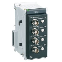
Acceleration measurement unit
|
Model |
NR-CA04 *1 |
|||
|
Image |
|
|||
|
Type |
Acceleration measurement unit |
|||
|
Input method |
Charge output sensor input / Single-end input, channels not insulated from each other; input channels switchable between insulated and not insulated from other units (PC) |
|||
|
Number of channels |
4 ch*2 |
|||
|
Measurement cycle |
Maximum sampling cycle: 10 µs (100 kHz) to 60 s |
|||
|
A/D converting system |
Delta-sigma method, simultaneous sampling of all channels |
|||
|
A/D resolution |
24 bit |
|||
|
Low pass filter |
PASS, 100 Hz, 1 kHz, 10 kHz (−12 dB/oct) |
|||
|
Maximum input rating |
±25 V |
|||
|
±50,000 pC |
||||
|
Withstand voltage |
Input to system bus/earth |
300 VAC (50/60 Hz) for 1 minute |
||
|
Connector format |
Charge output sensor input: Miniature (10-32UNF); Voltage input/output (built-in pre-amplifier) |
|||
|
Input impedance |
100 kΩ ±1%, approx. 38 pF |
|||
|
Input type |
Sensor input |
±50000 m/s2 ±164042.0 ft/s2, ±20000 m/s2 ±65616.8 ft/s2, ±10000 m/s2 ±32808.4 ft/s2, ±5000 m/s2 ±16404.2 ft/s2, |
||
|
Voltage input |
±10 V, ±5 V, ±2 V, ±1 V, ±500 mV, ±200 mV, ±100 mV, ±50 mV |
|||
|
Input coupling |
Sensor input |
Charge output / Voltage output (built-in pre-amplifier) / Charge output - RMS / |
||
|
Voltage input |
AC/DC/AC-RMS/DC-RMS |
|||
|
Input frequency band |
Electric charge output type |
1.5 Hz (−3 dB typ.) to 45 kHz (±0.5 dB) |
||
|
Voltage output type (with built-in preamplifier) AC/AC-RMS |
1.0 Hz (−3 dB typ.) to 45 kHz (±0.5 dB) |
|||
|
DC/DC-RMS |
45 kHz DC max. (±0.5 dB) |
|||
|
Measurement accuracy |
Electric charge output type |
±0.9% of F.S. at [Sensor sensitivity] × [Setting range] ≥ 20 pC |
||
|
Voltage output type (with built-in preamplifier) |
±0.25% of F.S. at [Sensor sensitivity] × [Setting range] ≥ 200 mV |
|||
|
Voltage |
±10 V to ±100 mV range: ±0.1% of F.S. |
|||
|
Measurement range |
±10 V |
Measurable range: −11.0000 to +11.0000 V, Display resolution: 0.5 mV*3 |
||
|
±5 V |
Measurable range: −5.5000 to +5.5000 V, Display resolution: 0.2 mV*3 |
|||
|
±2 V |
Measurable range: −2.2000 to +2.2000 V, Display resolution: 100 μV*3 |
|||
|
±1 V |
Measurable range: −1.1000 to +1.1000 V, Display resolution: 50 μV*3 |
|||
|
±500 mV |
Measurable range: −550.00 to +550.00 mV, Display resolution: 20 μV*3 |
|||
|
±200 mV |
Measurable range: −220.00 to +220.00 mV, Display resolution: 10 μV*3 |
|||
|
±100 mV |
Measurable range: −110.000 to +110.000 mV, Display resolution: 5 μV*3 |
|||
|
±50 mV |
Measurable range: −55.000 to +55.000 mV, Display resolution: 2 μV*3 |
|||
|
±50000 m/s2 ±164042.0 ft/s2 |
Measurable range: −55000 to +55000 m/s2 -180446.2 ft/s2 to +180446.2 ft/s2, Display resolution: 2 m/s2 6.6 ft/s2*3 |
|||
|
±20000 m/s2 ±65616.8 ft/s2 |
Measurable range: −22000 to +22000 m/s2 -72178.5 ft/s2 to +72178.5 ft/s2, Display resolution: 1 m/s2 3.3 ft/s2*3 |
|||
|
±10000 m/s2 ±32808.4 ft/s2 |
Measurable range: −11000 to +11000 m/s2 -36089.2 ft/s2 to +36089.2 ft/s2, Display resolution: 0.5 m/s2 1.6 ft/s2*3 |
|||
|
±5000 m/s2 ±16404.2 ft/s2 |
Measurable range: −5500 to +5500 m/s2 -18044.6 ft/s2 to +18044.6 ft/s2, Display resolution: 0.2 m/s2 0.7 ft/s2*3 |
|||
|
±2000 m/s2 ±6561.7 ft/s2 |
Measurable range: −2200 to +2200 m/s2 -7217.8 ft/s2 to +7217.8 ft/s2, Display resolution: 0.1 m/s2 0.3 ft/s2*3 |
|||
|
±1000 m/s2 ±3280.8 ft/s2 |
Measurable range: −1100 to +1100 m/s2 -3608.9 ft/s2 to +3608.9 ft/s2, Display resolution: 0.05 m/s2 0.16 ft/s2*3 |
|||
|
±500 m/s2 ±1640.4 ft/s2 |
Measurable range: −550 to +550 m/s2 -1804.5 ft/s2 to +1804.5 ft/s2, Display resolution: 0.02 m/s2 0.07 ft/s2*3 |
|||
|
±200 m/s2 ±656.2 ft/s2 |
Measurable range: −220 to +220 m/s2 -728.1 ft/s2 to +728.1 ft/s2, Display resolution: 0.01 m/s2 0.03 ft/s2*3 |
|||
|
±100 m/s2 ±328.1 ft/s2 |
Measurable range: −110 to +110 m/s2 -360.9 ft/s2 to +360.9 ft/s2, Display resolution: 0.005 m/s2 0.0164 ft/s2*3 |
|||
|
±50 m/s2 ±164.0 ft/s2 |
Measurable range: −55 to +55 m/s2 -180.4 ft/s2 to +180.4 ft/s2, Display resolution: 0.002 m/s2 0.0066 ft/s2*3 |
|||
|
±20 m/s2 ±65.6 ft/s2 |
Measurable range: −22 to +22 m/s2 -72.2 ft/s2 to +72.2 ft/s2, Display resolution: 0.001 m/s2 0.0033 ft/s2*3 |
|||
|
±10 m/s2 ±32.8 ft/s2 |
Measurable range: −11 to +11 m/s2 -36.1 ft/s2 to +36.1 ft/s2, Display resolution: 0.0005 m/s2 0.0016 ft/s2*3 |
|||
|
±5 m/s2 ±16.4 ft/s2 |
Measurable range: −5.5 to +5.5 m/s2 -18.0 ft/s2 to +18.0 ft/s2, Display resolution: 0.0002 m/s2 0.0007 ft/s2*3 |
|||
|
±2 m/s2 ±6.6 ft/s2 |
Measurable range: −2.2 to +2.2 m/s2 -7.2 ft/s2 to +7.2 ft/s2, Display resolution: 0.0001 m/s2 0.0003 ft/s2*3 |
|||
|
±1 m/s2 ±3.3 ft/s2 |
Measurable range: −1.1 to +1.1 m/s2 -3.6 ft/s2 to +3.6 ft/s2, Display resolution: 0.00005 m/s2 0.000164 ft/s2*3 |
|||
|
Buffer memory |
16M data*4 |
|||
|
Warm up time |
30 minutes or more*5 |
|||
|
Calculationfunction |
Single integration (velocity conversion), Double integration (displacement conversion) |
|||
|
Sensor input sensitivity setting range |
Electric charge output type |
0.01000 to 999.9 pC/(m/s2) |
||
|
Voltage output type (with built-in preamplifier) |
0.01000 to 999.9 mV/(m/s2) |
|||
|
Anti-aliasing filter |
fc = Sampling frequency × 49%, −100 dB at sampling frequency |
|||
|
Common mode noise reduction ratio |
80 dB or more (at max. 60 Hz DC) (typ.) |
|||
|
Crosstalk noise reduction ratio |
100 dB or more (typ.) |
|||
|
High pass filter |
PASS, 10 Hz (−12 dB/oct) |
|||
|
Disconnection detection function |
Available (voltage output (built-in pre-amplifier) models only) |
|||
|
Disconnection detection cycle |
Approx. 200 ms |
|||
|
RMS amplitude accuracy |
Sine wave: 20 Hz to 1 kHz, ±0.5% of F.S. |
|||
|
Residual noise level |
Electric charge output type |
±0.01% of F.S. (typ.) at [Sensor sensitivity] × [Setting range] ≥ 50 pC |
||
|
Voltage output type (with built-in preamplifier) |
±0.05% of F.S. (typ.) at [Sensor sensitivity] × [Setting range] ≥ 200 mV |
|||
|
Voltage |
10 to 200 mV range: ±0.01% of F.S. (typ.) |
|||
|
Sensor power supply |
22 V ±10% / 4 mA ±20% |
|||
|
TEDS information |
Read sensor information |
|||
|
Rating |
Power consumption |
3.8 W or less |
||
|
Environmental resistance |
Ambient temperature |
0 to +40°C 32°F to 104°F |
||
|
Relative humidity |
10 to 85% RH (no condensation) |
|||
|
Weight |
Approx. 270 g 9.53 oz |
|||
|
*1 The above specifications are the values when zero point adjustment is performed after the warm-up period in an environment with a temperature of 23°C ±3°C 73.4°F ±5.4°F. |
||||
Pulse measurement unit
|
Model |
NR-FV04 *1 |
|||
|
Image |
|
|||
|
Type |
Pulse measurement unit |
|||
|
Input method |
Insulated single-end input, channels insulated from each other, input channels insulated from other units (PC) |
|||
|
Number of channels |
4 ch *2 |
|||
|
Measurement cycle |
Maximum sampling cycle: 1 μs (1 MHz) to 60 s |
|||
|
A/D converting system |
Successive approximation, simultaneous sampling of all channels |
|||
|
A/D resolution |
14 bit |
|||
|
Input frequency band |
250 kHz (−3 dB or more) |
|||
|
Low pass filter |
PASS, 1.5 kHz, 15 kHz, 50 kHz |
|||
|
Pulse input |
Input type |
Pulse frequency, pulse count (Single-phase input) |
||
|
Maximum input voltage |
±700 V *3 |
|||
|
Threshold voltage |
+100 V, +50 V, +20 V, +10 V, +5 V, +2.5 V, +1 V, +500 mV, +250 mV, +100 mV, +50 mV, 0 V |
|||
|
Minimum pulse duration |
2 μs or more for both ON and OFF |
|||
|
Hysteresis |
AUTO, 100 mV, 500 mV, 5 V |
|||
|
Pulse divisions |
1 to 64 (Can be set to units of 1 division) |
|||
|
Input coupling |
DC rising edge, DC falling edge, AC rising edge, AC falling edge |
|||
|
Digital filter |
Pulse frequency: Averaging rate of 1 to 32768 (automatically selected), Pulse count: None |
|||
|
Predictive functions |
Predictive calculation, Stop prediction (OFF, ×1.5, ×3, ×5, ×8, ×16) |
|||
|
Sensor power output |
Dedicated connectors for OP-88003 (AUX POWER) × 2 when using OP-88003; +12 V, 50 mA or +5 V, 50 mA |
|||
|
Voltage input |
Input type |
±100 V, ±50 V, ±20 V, ±10 V, ±5 V, ±2 V |
||
|
Maximum input voltage |
±700 V *3 |
|||
|
Digital filter |
Averaging rate: 1 to 128 (automatically selected) |
|||
|
Input coupling |
DC, AC |
|||
|
Common mode noise reduction ratio |
80 dB or more (at up to 60 Hz DC) |
|||
|
Residual noise level |
0.02% of F.S., LPF: 1.5 kHz (200 μs/S, digital filter: ON); 0.05% of F.S., LPF: PASS |
|||
|
Measurement range |
Pulse frequency |
Measurable range: 0.05 to 16000.00 Hz, Display resolution: 0.01 to 1.00 Hz (selected automatically according to frequency) |
||
|
Pulse count |
Measurable range: 0 to 65,000 counts/sampling cycle, Display resolution: 1 count |
|||
|
±100 V |
Measurable range: −110.000 to +110.000 V, Display resolution: 5 mV |
|||
|
±50 V |
Measurable range: −55.000 to +55.000 V, Display resolution: 2 mV |
|||
|
±20 V |
Measurable range: −22.000 to +22.000 V, Display resolution: 1 mV |
|||
|
±10 V |
Measurable range: −11.0000 to +11.0000 V, Display resolution: 0.5 mV |
|||
|
±5 V |
Measurable range: −5.5000 to +5.5000 V, Display resolution: 0.2 mV |
|||
|
±2 V |
Measurable range: −2.2000 to +2.2000 V, Display resolution: 0.1 mV |
|||
|
Measurement accuracy |
Pulse frequency |
±0.07% of rdg, ±0.01 Hz (20 Hz to 15 kHz, 20 ms/S, with digital filter ON) |
||
|
Voltage input |
±0.1% of F.S. |
|||
|
Withstand voltage |
Input to system bus/earth |
2200 VAC (50/60 Hz) for 1 minute |
||
|
Connector format |
Insulated BNC connector |
|||
|
Input impedance |
1 MΩ ±1%, approx. 30 pF |
|||
|
Buffer memory |
16M data*4 |
|||
|
Warm up time |
30 minutes or more |
|||
|
Maximum allowable voltage to ground |
[When using OP-35409 1:1 voltage-resistant probe] Measurement terminal, GND terminal: 300 Vrms (CAT II); |
|||
|
Rating |
Power consumption |
4 W or less (including OP-88003 sensor power supply) |
||
|
Environmental resistance |
Insulation resistance |
500 VDC, 10 MΩ or more |
||
|
Ambient temperature |
0 to +40°C 32°F to 104°F |
|||
|
Relative humidity |
10 to 85% RH (no condensation) |
|||
|
Weight |
Approx. 270 g 9.53 oz |
|||
|
*1 The above specifications are the values when zero point adjustment is performed after the warm-up period in an environment with a temperature of 23°C ±3°C 73.4°F ±5.4°F. |
||||

CAN data collection unit
|
Model |
NR-C512*1 |
|||
|
Image |
|
|||
|
Protocol |
Supported protocol |
CAN Ver. 2.0B |
||
|
Supported physical layers |
High speed: ISO 11898 |
|||
|
Communication speed |
High speed: 60 kbps to 1 Mbps |
|||
|
Port |
Number of ports |
1 port*2 |
||
|
Design |
9-pin D-sub male |
|||
|
Maximum number of messages/maximum number of signals |
128 messages/port, |
|||
|
Collection period |
Maximum sampling cycle: 200 µs |
|||
|
Power source for the CAN bus |
High speed: 5 V internal supply |
|||
|
Built-in termination resistor |
High speed: 120 Ω × 2 (enabled/disabled with DIP switch) |
|||
|
Manual transmission/reception |
Transmission/reception by specifying message ID and data |
|||
|
Withstand voltage |
Measurement input terminal - System bus |
300 VAC (50/60 Hz) for 1 minute |
||
|
Rating |
Power consumption |
1.6 W or less |
||
|
Environmental resistance |
Ambient temperature |
0 to +40°C 32°F to 104°F |
||
|
Relative humidity |
10 to 85% RH (no condensation) |
|||
|
Weight |
Approx. 150 g 5.30 oz |
|||
|
*1 High speed and Single wire modes cannot be used at the same time. |
||||

Ethernet data collection unit
|
Model |
NR-EN16 |
|||
|
Image |
|
|||
|
Connection target devices |
DL-EN1 (Connected sensor: GT2 Series, GT Series, IL Series, IG Series, IB Series, IX Series, SK Series)*1 |
|||
|
Connection target device identification |
Automatic identification or manual identification by specifying the IP address |
|||
|
Communication protocols |
Ethernet TCP/UDP communication, BOOTP/DHCP client supported (compatible with the above connection target devices) |
|||
|
Interface |
Ethernet 100Base-TX (AUTO-MDI/MDIX-compatible), 1 port*2 |
|||
|
Number of channels |
16 ch max. (varies depending on connected devices) |
|||
|
Collection period |
Maximum sampling cycle: 1 ms (1 kHz) to 60 s |
|||
|
Buffer memory |
8M data*4 |
|||
|
Sensor power output function |
• Output from power supply output connector (4-pole terminal block) (switchable between output ON and OFF) |
|||
|
Power consumption |
1.6 W or less*5 |
|||
|
Surrounding air temperature |
0 to +40°C 32°F to 104°F |
|||
|
Operating ambient humidity |
10 to 85% RH (no condensation) |
|||
|
Weight |
Approx. 150 g 5.30 oz (including approx. 10 g 0.35 oz for the OP-88513 (NR-EN16 power supply terminal block)) |
|||
|
*1 Multiple sensors can be connected to each DL-EN1/NQ-EP4L. The number of connectable sensors depends on the DL-EN1/NQ-EP4L. |
||||

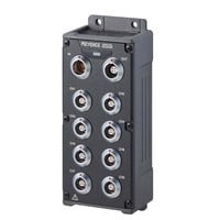
Environment-resistant temperature measurement unit
|
Model |
NR-XTH08T |
|||
|
Image |
|
|||
|
Input method |
Insulated single-end input, channels insulated from each other, input channels insulated from the case and other units (system) |
|||
|
Number of input channels |
8*1 |
|||
|
Input connector type |
Miniature thermocouple connector (Universal type) |
|||
|
Measurement cycle |
Maximum sampling cycle: 10 ms (100 Hz) to 1 h |
|||
|
A/D converting system |
Delta-sigma method |
|||
|
A/D resolution |
24 bits |
|||
|
A/D integration time (noise filter) |
AUTO (Automatic configuration according to sampling cycle), 2.5 ms (400 Hz), 16.7 ms (60 Hz), 20 ms (50 Hz), 100 ms (10 Hz) |
|||
|
Input type |
Thermocouple: K, J, E, T, R, S, B, N, C |
|||
|
Low pass filter |
PASS / 200 Hz / 20 Hz |
|||
|
Averaging |
Switchable between ON/OFF, Averaging rate: 2 to 128 (moving average) |
|||
|
Reference contact compensation |
Switchable between internal and external |
|||
|
Reference contact compensation accuracy |
±0.5°C ±0.9°F (23°C ±3°C 73.4°F ±5.4°F at input terminal temperature equilibrium) |
|||
|
Maximum input rating |
±30 V*2 |
|||
|
Maximum allowable input ground voltage |
Dry locations: 30 VAC and 42.4 Vpeak, or 60 VDC |
|||
|
Withstand voltage |
Between measurement input terminal and case/other units (system): 1000 VAC (50 Hz / 60 Hz) for 1 minute |
|||
|
Input impedance |
10 MΩ or more |
|||
|
Input signal source resistance |
2 kΩ or less |
|||
|
Thermocouple burnout detection |
Switchable between ON/OFF, When ON: Approx. 10 μA current detection*3 |
|||
|
Measurable range |
K: −100 to +1372°C -148°F to +2501.6°F, −200 to −100°C -328°F to -148°F |
|||
|
Measurement accuracy |
K: ±0.04% of rdg ±0.4°C ±0.7°F, ±0.43% of rdg ±0.1°C ±0.2°F |
|||
|
Display resolution |
K: 0.05°C 0.09°F |
|||
|
Buffer memory |
16M data*5 |
|||
|
Warm up time |
30 minutes or more |
|||
|
Common mode noise reduction ratio |
135 dB or more (up to 60 Hz DC) (typ.) *4 |
|||
|
Remote connection |
Dedicated environment-resistant remote unit input port × 1 (Remote IN), output port × 1 (Remote OUT) |
|||
|
Synchronization accuracy between remote connection units |
±1 μs*7 |
|||
|
Power supply |
Supplied from NR-X100W master unit |
|||
|
Power consumption |
5.0 W max. |
|||
|
Surrounding air temperature |
−40 to +85°C -40°F to +185°F*8 |
|||
|
Operating ambient humidity |
Max. 100% RH*9 |
|||
|
Vibration resistance |
100 m/s2 328.1 ft/s2; 5 to 2000 Hz; 2 hours in each of the X, Y, and Z directions (IEC 60068-2-6)*10 |
|||
|
Shock resistance |
1000 m/s2 3280.8 ft/s2; 3 times in each of the X, Y, and Z directions (18 times in total) (IEC 60068-2-27) |
|||
|
Enclosure rating |
IP65/IP67 (IEC 60529) |
|||
|
Material |
Main unit case: Aluminum die-casting (coated) / PBT+PC / PC, Display: Reinforced glass, |
|||
|
Weight |
Approx. 660 g 23.30 oz |
|||
|
*1 Max. expansion: 64 ch (with 8 units connected, using NR-X100W) |
||||

Environment-resistant analog measurement unit
|
Model |
NR-XHA08T |
|||
|
Image |
|
|||
|
Input method |
Insulated single-end input, channels insulated from each other, input channels insulated from the case and other units (system) |
|||
|
Number of input channels |
8*1 |
|||
|
Input connector type |
Dedicated 3-pin connector |
|||
|
Measurement cycle |
Maximum sampling cycle: 100 μs (10 kHz) to 60 s |
|||
|
A/D converting system |
Delta-sigma method |
|||
|
A/D resolution |
24 bits |
|||
|
A/D integration time (noise filter) |
AUTO (Automatic configuration according to sampling cycle), 25 μs (40 kHz), 208 μs (4.8 kHz), 2.5 ms (400 Hz), 16.7 ms (60 Hz), 20 ms (50 Hz), 100 ms (10 Hz) |
|||
|
Input frequency band |
2 kHz (−3 dB or more) |
|||
|
Input type |
Voltage input: ±60 V, ±20 V, ±10 V, ±5 V, ±2 V, ±1 V, ±500 mV, ±200 mV, ±100 mV |
|||
|
Averaging |
Switchable between ON/OFF, Averaging rate: 2 to 128 (moving average) |
|||
|
Input impedance |
Voltage input ±2 V range or higher |
1 MΩ ±2% |
||
|
Voltage input ±1 V range or higher |
10 MΩ ±2% |
|||
|
Current input |
Approx. 100 Ω |
|||
|
Measurement range |
±60 V |
Measurable range: −60.000 to +60.000 V |
||
|
±20 V |
Measurable range: −22.000 to +22.000 V |
|||
|
±10 V |
Measurable range: −11.000 to +11.000 V |
|||
|
±5 V |
Measurable range: −5.5000 to +5.5000 V |
|||
|
±2 V |
Measurable range: −2.2000 to +2.2000 V |
|||
|
±1 V |
Measurable range: −1.1000 to +1.1000 V |
|||
|
±500 mV |
Measurable range: −550.00 to +550.00 mV |
|||
|
±200 mV |
Measurable range: −220.00 to +220.00 mV |
|||
|
±100 mV |
Measurable range: −110.000 to +110.000 mV |
|||
|
±20 mA |
Measurable range: −22.000 to +22.000 mA |
|||
|
Maximum input rating |
Voltage input: ±60 V, Current input: ±30 mA |
|||
|
Maximum allowable input ground voltage |
120 VAC and 170 Vpeak, or 120 VDC (when using NR-XHA08T protective grounding) |
|||
|
Withstand voltage |
Between measurement input terminal and case/other units (system): 1000 VAC (50 Hz / 60 Hz) for 1 minute |
|||
|
Buffer memory |
16M data*3 |
|||
|
Warm up time |
30 minutes or more |
|||
|
Residual noise level |
0.005% of F.S. (typ.) when A/D integration time is set to 20 ms (50 Hz) / 16.7 ms (60 Hz) |
|||
|
Common mode noise reduction ratio |
105 dB or more (up to 60 Hz DC) (typ.)*2 |
|||
|
Remote connection |
Dedicated environment-resistant remote unit input port × 1 (Remote IN), Output port × 1 (Remote OUT) |
|||
|
Synchronization accuracy between remote connection units |
±1 μs*5 |
|||
|
Power supply |
Supplied from NR-X100W master unit |
|||
|
Power consumption |
5.8 W or less |
|||
|
Surrounding air temperature |
−40 to +85°C -40°F to +185°F*6 |
|||
|
Operating ambient humidity |
Max. 100% RH*7 |
|||
|
Vibration resistance |
100 m/s2 328.1 ft/s2; 5 to 2000 Hz; 2 hours in each of the X, Y, and Z directions (IEC 60068-2-6)*8 |
|||
|
Shock resistance |
1000 m/s2 3280.8 ft/s2; 3 times in each of the X, Y, and Z directions (18 times in total) (IEC 60068-2-27) |
|||
|
Enclosure rating |
IP65/IP67 (IEC 60529) |
|||
|
Material |
Main unit case: Aluminum die-casting (coated), Display: Reinforced glass, Connectors: Brass (chromate processing), Connector protection cap: PBT+PC |
|||
|
Weight |
Approx. 690 g 24.36 oz |
|||
|
*1 Max. expansion: 64 ch (with 8 units connected, using NR-X100W) |
||||