I/O Circuit Connection diagram
* Download CAD file or product manual for larger image/text and more detail.
NPN
GT-71/72/75/76
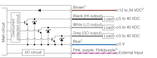
1. Brown and blue are applicable only to main units (GT-71A/71AP/75A/75AP), not to expansion units (GT-72A/72AP/76A/76AP). The power lines for sub units are internally connected to the main unit.2. At expansion, 12 VDC changes to 24 VDC.3. For details on external input, see the External Input Circuit Diagram.
External Input circuit
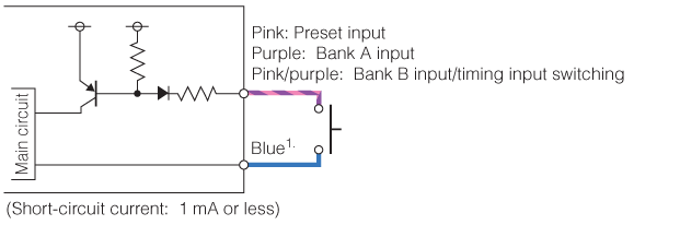
1. Brown and blue are applicable only to main units (GT-71A/71AP/75A/75AP), not to expansion units (GT-72A/72AP/76A/76AP). The power lines for sub units are internally connected to the main unit.2. At expansion, 12 VDC changes to 24 VDC.3. For details on external input, see the External Input Circuit Diagram.