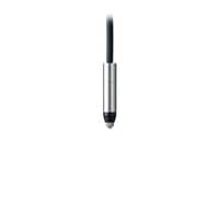
High-Accuracy Digital Contact Sensor
GT2 series
Sensor head: Short-range pencil type GT2-S1

*Please note that accessories depicted in the image are for illustrative purposes only and may not be included with the product.
Specifications
Model | GT2-S1*1 | |||
Detection system | Differential transformer | |||
Measuring range | 1 mm 0.04"*2 | |||
Operating range | 2 mm 0.08"*2 | |||
Resolution | 0.1 µm | |||
Indicated accuracy | 1 µm (P-P)*3*4 | |||
Measuring force | Downward mounting | 1.12 N*5 | ||
Side mounting | 1.1 N*5 | |||
Upward mounting | 1.08 N*5 | |||
Sampling cycle | 1 ms | |||
Mechanical response | 40 Hz*4 | |||
Operation indicator light | 2-color LED (red, green) | |||
Environmental resistance | Enclosure rating | IP67G (JIS)*6, IP67 (IEC) | ||
Ambient temperature | -10 to +55 °C 14 to 131 °F (No freezing) | |||
Relative humidity | 10 to 85 % RH (No condensation) | |||
Vibration resistance | 10 to 55 Hz, Double amplitude 1.5 mm 0.06", 2 hours in each of the X, Y, and Z directions | |||
Shock resistance | 1,000 m/s2 (IEC60068-2-27) | |||
Materials | Main body | Main body case: SUS440C, Sensor head-relay connector cable: PUR, Relay amplifier: PPSU | ||
Dust boot | NBR | |||
Contact | SUS304, cemented tungsten carbide*7 | |||
Sensor head cable | Optional (connect to relay connector) | |||
Weight | Approx. 30 g (not including cable)*8 | |||
*1 Note: You may not be able to connect the sensor head to the amplifier unit depending on when the amplifier unit was purchased. For details, contact your local sales office. | ||||


![NR-X Data Logger / Data Acquisition Direct connection to other KEYENCE products [Click Here to Learn More!]](/Images/nr-x_series_300_300_01_2089589.jpg)