![Learn the Basics of Continuous Inkjet Printers [CIJ Central]](/Images/ss_products_inkjet_header_title_1785688.gif)
Example: MK-G Series
This section will use the KEYENCE MK-G Series as an example to explain the structure and features of an inkjet printer.
Controller
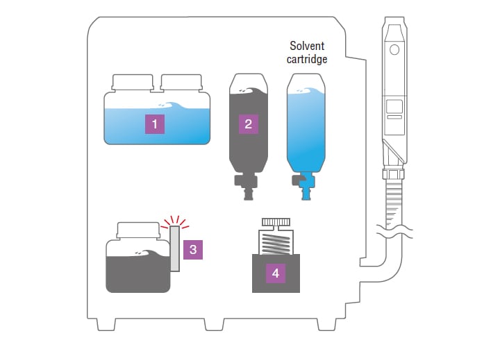
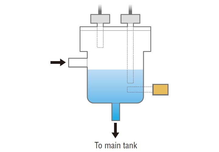
Conditioning tankKEYENCE original
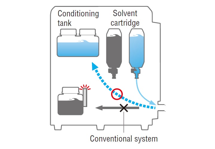
The solvent used during automatic cleaning performed on startup, shut down, and maintenance is collected in the conditioning tank.
This conditioning tank is used to prevent dilution of the ink in the main tank and control the viscosity of the ink. Since the ink is a conductive fluid, a level gauge using an electrode is used to manage the charge in the conditioning tank.
* Generally, inkjet printers do not have a conditioning tank, so the solvent is collected in the main tank, which leads to ink dilution.
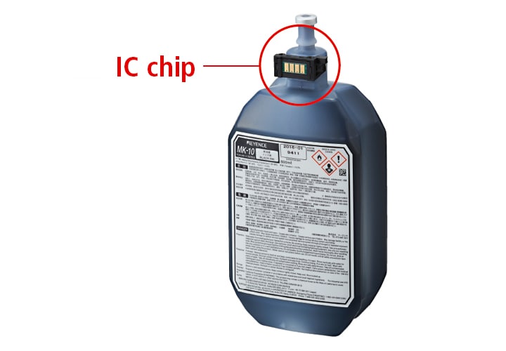
Ink cartridge
Ink can be fed into the system in one of two ways: the ink tank can be filled from a bottle, or an ink cartridge can be inserted.
Advantages to using cartridges with IC chips
- Prevents incorrect insertions
- If the ink or solvent type is incorrect, the user will be notified by an error.
- Possible to check the remaining amount
- The remaining amount of fluid is displayed as a percentage.
- Equipped with an empty detection sensor
- The cartridge can be used until it is completely empty.
Viscometer
The viscometer monitors the viscosity within the main tank at all times in order to maintain the optimum viscosity. The ink from the main tank is brought into the viscometer, which feeds information back in order to correct the viscosity levels. Additionally, the temperature of the ink inside the viscometer is measured to adjust the viscosity for that particular temperature.
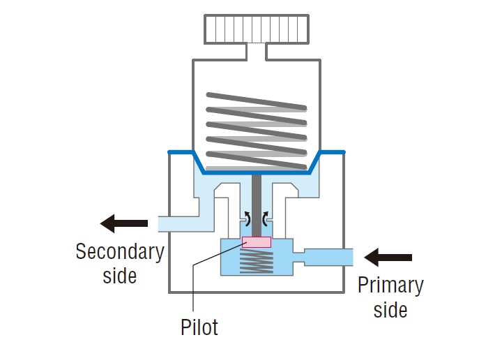
Decompression valve
Because a pump is used, the pressure on the primary side is not fixed. A decompression valve is used to maintain a constant pressure on the secondary side. The decompression valve is a self-actuated pressure regulating valve that is activated by the pressure of the fluid.
If the pressure on the secondary side is low, the pilot is lowered, which increases the flow of ink to the secondary side and thereby increases the pressure. On the other hand, if the pressure is high, the pilot is raised, which stops the flow of ink to the secondary side and thereby keeps the pressure constant.
Print head
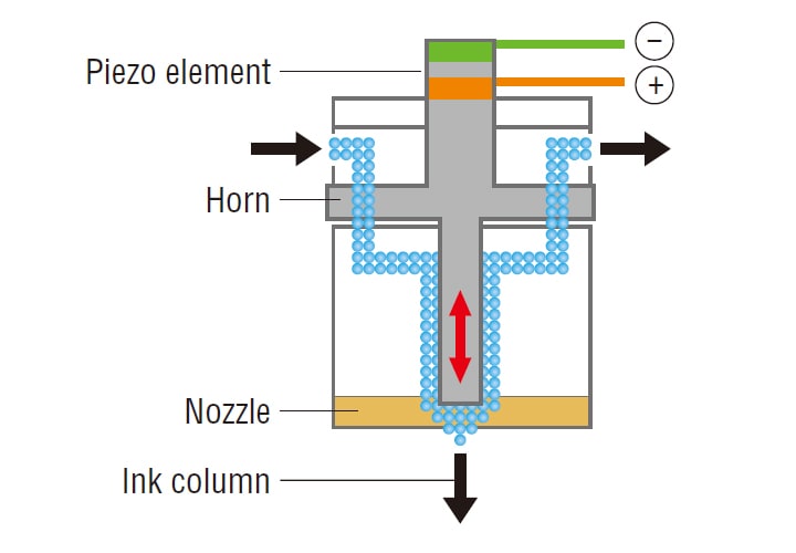
Cannon (piezo element and nozzle)
Inside the cannon, a cylindrical part known as the horn vibrates up and down to create ink particles from the ink column.
The source of the vibrations is the piezoelectric element, or piezo element. Vibrations are generated by a characteristic of this
element: its volume changes when a voltage is applied to it.
This element is attached to the horn, and this creates approximately 70,000 ink particles per second. The cannon has a path for feeding ink and a path for collecting ink. During operation, a solenoid valve is used to close the collection path, and the cannon discharges ink from the nozzle.
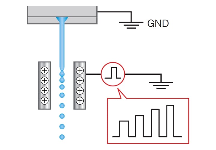
Charging electrode plates
The ink discharged from the nozzle in the shape of a column passes through the charging electrode plates, which adjust the ink so that it is separated into ideal ink particles. Pulse voltage is applied to the charging electrode plates, and the amount of negative electric charge saturation in the ink column varies depending on the size of the pulses. Immediately after the ink particles are formed, the amount of electric charge given to each ink particle is varied so that each particle has a (negative) voltage that corresponds to the print dot position information.
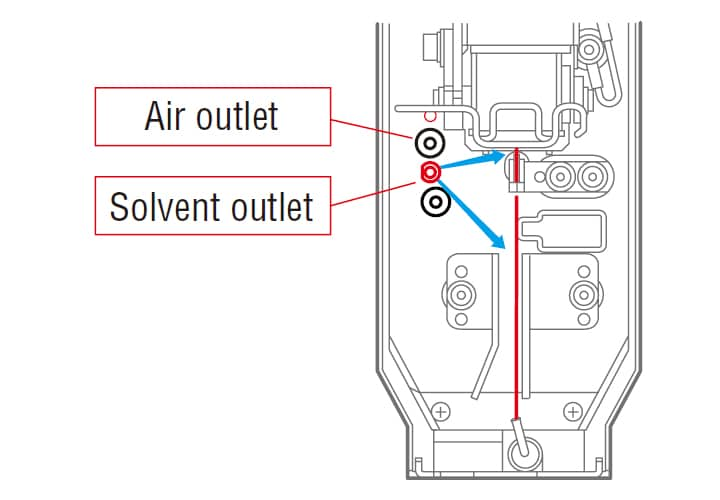
Auto-showerKEYENCE original
If the inside of the print head is dirty, it will not be possible to print correctly. The KEYENCE MK-G Series is equipped with an automatic cleaning and drying function! The nozzle, charging electrode plates, and deflecting electrode plates are all sprayed with high-pressure cleaning fluid. After cleaning, the inside of the print head is dried.
Deflecting electrode plates
A high voltage is applied to the deflecting electrode plates, which causes an electric field to form. When the negatively charged ink particles pass through the deflecting electrode plates, the ink particles are deflected according to their charge.
* An electric field always forms around an object to which voltage is applied.

Charge sensor
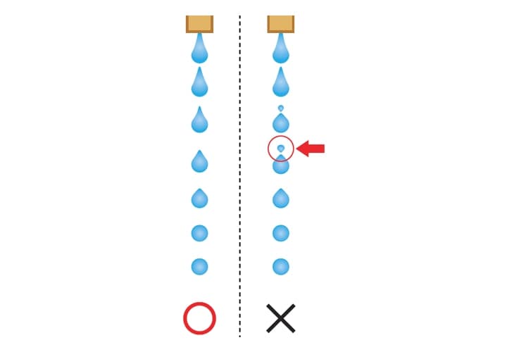
Monitoring the status of particles
The ink viscosity is constantly changing. When the ink viscosity changes, the timing with which ink particles are made and the amount of charge applied also changes, which may lead to defects such as unstable text. In this situation, it is necessary to adjust the piezo voltage. The time it takes for charged particles to pass a sensor is fed back to adjust the electrical charge applied.
- Automatic ink particle optimizationKEYENCE original
- The KEYENCE MK-G Series senses the position at which ink is separated into particles and adjusts the piezo voltage. This voltage is determined by measuring the time it takes for the ink particles to pass the charge sensor. Conventionally, it was necessary to adjust the piezo voltage manually.


![Inkjet Printer Tech Guide [Basic Knowledge Edition]](/img/asset/AS_114378_L.jpg)