
Dimensional Measurement of Heat Exchangers
Heat exchangers are vital to working with heat in processes. For example, many heat exchangers are installed as naphtha thermal cracking devices (ethylene devices) in petrochemical processes in Japan.
There are many different types of heat exchangers and they are used for various purposes. This section explains the structures and types with a focus on shell and tube heat exchangers (which are widely used in processes). That is, this section explains the basic knowledge required for dimensional measurement. It also introduces dimensional measurement points and problems as well as solutions to these problems with our latest measurement system.
- What Is a Heat Exchanger?
- Heat Exchanger Types and Structures
- Necessity of Dimensional Measurement of Heat Exchangers
- Dimensional Measurement of Heat Exchangers
- Problems of Dimensional Measurement of Heat Exchangers and Their Solutions
- Optimization of Dimensional Measurement of Heat Exchangers

What Is a Heat Exchanger?
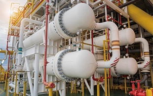
A heat exchanger is a device that transmits heat from a hot object to a cold one. Regardless of whether they are solids, liquids, or gases, objects have the property of moving from high temperatures to low temperatures. Heat exchangers use this property to efficiently move heat. Typically, a liquid is used for the medium that transfers heat.
Heat Exchanger Types and Structures
Heat exchangers are classified according to factors such as their structures and flow methods. In terms of structure, they are broadly classified into tube types and plate types. Tube types include multi-tube types, single-tube types, and double-tube types. Plate types include spiral types and jacket types.
One example of multi-tube types is shell and tube heat exchangers, which provide a large heat transfer surface area with minimal space restraints. Because they can also keep the fluid pressure loss low, shell and tube heat exchangers are widely used in processes.
This section explains the types and structures of shell and tube heat exchangers. Understanding the structural characteristics of each heat exchanger is vital for correct dimensional measurement.
Shell and tube heat exchanger types
There are three types of shell and tube heat exchangers: fixed tube sheet heat exchangers, floating head heat exchangers, and U-tube heat exchangers.
Fixed tube sheet heat exchanger
In a fixed tube sheet heat exchanger, the tubes are attached via tube expansion or welding to a tube sheet fixed to the shell. The simple structure provides this type with the advantage of being manufacturable at low cost. On the other hand, the shell cannot be cleaned, so this type is not suited to converting heat with a shell-side fluid that is heavily dirty or corrosive. Furthermore, caution regarding the thermal expansion of the shell and tubes is necessary. Expansion joints are used in the shell when the difference in fluid temperature between the shell and tubes is large.
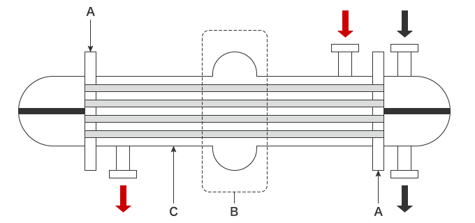
- A
- Tube sheet
- B
- Expansion joint
- C
- Shell
- Black arrows
- Tube-side fluid
- Red arrows
- Shell-side fluid
Floating head heat exchanger
In a floating head heat exchanger, one side of the tube bundle is attached to a fixed tube sheet and the other side is attached via tube expansion or welding to a floating tube sheet. Because the shell and tube bundle are not joined together, they can freely undergo thermal expansion. Also, it is easy to attach and detach the tube bundle, allowing for maintenance such as cleaning, inspection, and repairs.
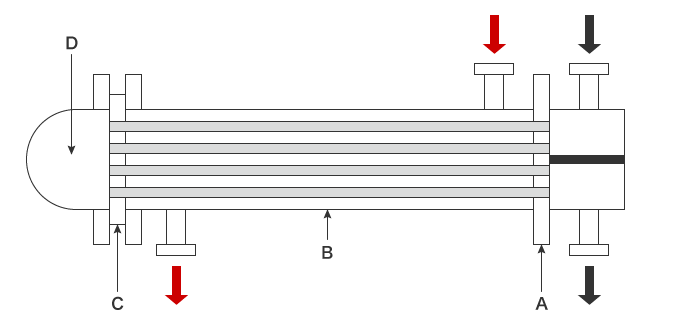
- A
- Tube sheet
- B
- Shell
- C
- Floating head tube sheet
- D
- Shell cover
- Black arrows
- Tube-side fluid
- Red arrows
- Shell-side fluid
U-tube heat exchanger
In a U-tube heat exchanger, tubes are bent into U shapes before being inserted into the shell. Because the shell and tubes are not joined together, they can freely deform due to thermal expansion just like floating head heat exchangers. Also, the tube bundle can be attached and detached, allowing for easy maintenance. However, the U-shaped part of the tubes is difficult to clean.
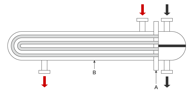
- A
- Tube sheet
- B
- Shell
- Black arrows
- Tube-side fluid
- Red arrows
- Shell-side fluid
Shell and tube heat exchanger structure
A floating head heat exchanger is used as an example below to introduce the structure of shell and tube heat exchangers. A floating head heat exchanger is constructed from parts such as a shell cover, gaskets, a tube sheet, a channel, and a tube bundle. It is important to understand the positions and roles of these parts for the dimensional measurement of heat exchangers.
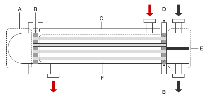
- A: shell cover
- A knuckle-shaped head is welded to flanges. The flanges join this cover to the shell.
- B: gaskets
- The gaskets are parts that increase the airtightness of items such as the channel cover, the space between the channel flanges and the tube sheet, the shell flanges, the shell, and the shell cover.
- C: shell
- The shell houses the tube bundle that converts the heat.
- D: tube sheet
- The tube sheet supports the tubes and separates the shell-side fluid and the tube-side fluid. Tube expansion is used to attach the tubes to the tube sheet, providing high airtightness and preventing fluid leaks.
- E: channel
- The channel is the entrance/exit for the tube-side fluid.
- F: tube bundle
- This bundle of tubes exchanges the heat. Most tube bundles are constructed from parts such as a tube sheet, tubes, and baffle plates.
Black arrows: tube-side fluid
Red arrows: shell-side fluid
Necessity of Dimensional Measurement of Heat Exchangers
The most important parts of a shell and tube heat exchanger are the tube bundle and the flanges. The tubes perform the heat exchange, and many tubes are housed with high density in a tube bundle. Hence, even minor errors in the dimensions or shapes of the tubes lead to mechanical stress. Furthermore, the flanges connect parts together, so their dimensions greatly affect the airtightness.
This section explains the necessity of and reasons for the dimensional measurements of these heat exchanger parts.
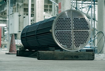
Tubes and tube bundles
The tubes are made of steel pipes designed to exchange heat (to transfer heat). Heat exchange steel pipes are grouped into two categories: seamless steel pipes and electric resistance welded steel pipes. Heat transfer steel pipes are used in hazardous applications where they are subjected to high temperatures and pressures, so strict design conditions, dimensional accuracy, and inspection standards are set on their materials.
However, tubes may be strained when they are welded to a tube sheet. Large heat exchangers have a total tube length of a few meters and a tube bundle diameter in excess of 2 m (6.6′). Small-aperture tubes must be assembled with high density into the tube bundle. Also, the tubes expand and contract due to high and low temperatures.
Therefore, the dimensional accuracy of the tubes must be measured strictly, and it is necessary to inspect the tube expansion part for strain and penetration due to welding. Furthermore, the small clearance between the tube bundle and the shell makes dimensional measurement of the overall segment shape of the tube bundle vital as well.
Flanges
A gasket is placed between flanges to ensure airtightness of the joint of parts. Therefore, low shape or dimensional accuracy of flanges leads to fluid leaks. For example, if a flange face is bent, the gasket receives an uneven force, making it impossible to achieve the designed airtightness. Additionally, if a flange face angle is not as designed on the basis of the axial direction, the flange is difficult to install and also is deformed by the tightening force of the bolts used to secure it. This deformation greatly decreases the strength of the flange.
For the reasons above, high accuracy is required for flange shapes and dimensions, especially those installed in areas exposed to high pressure. Furthermore, dimensional measurement is required not only during manufacturing but also during maintenance such as tube replacement and cleaning.
Dimensional Measurement of Heat Exchangers
This section explains the key points for dimensional measurements of shell and tube heat exchangers.
Dimensional measurement points
The most important measurement points for a shell and tube heat exchanger are the shapes and dimensions of the tubes and flanges.
This section explains the key points for dimensional measurements of these two parts.
Tubes and tube bundles
Important measurement points include not just the total length and outer diameter of the tubes but also coaxiality, which indicates the offset of a tube from the center of the axis, and the parallelism between tubes after tubes are attached to a tube bundle.
The pitch between tubes when attaching tubes to a tube bundle is determined by the tube outer diameter. If the tube outer diameter is 19 mm (3/4 in.), the pitch is 25 mm (0.9843″). If the tube outer diameter is 25.4 mm (1 in.), the pitch is 32 mm (1.2598″). The pitch is at least 1.2 times the outer diameter. Also, long tubes with lengths of 3 m (10 ft.) or 6 m (20 ft.) must be stored in a tube bundle with high density. A minor dimensional or shape error in a tube leads to mechanical stress in the parts when assembling the tube bundle, so these measurements must be carried out with especially high accuracy.
Flanges
Important measurement points of flange dimensions include the angle and perpendicularity of flange faces to the flange axial direction and the flatness of flange faces.
When flanges join a part to another part with bolts, a gasket is placed between them. The bolts apply strong tightening torque to the flanges to press the gasket, which ensures airtightness. In this situation, if the flange angle to the axial direction is not correct, the tightening torque will be uneven, possibly leading to partial gasket damage or flange deformation. Also, if tightened flange faces have defects, such as curvature, they may fail to press the gasket sufficiently. Flange dimensions and shapes need to be measured carefully because errors in these elements can lead to defective gasket engagement, causing fluid leakage, which is a large problem.
Problems of Dimensional Measurement of Heat Exchangers and Their Solutions
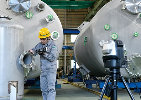
It is important to confirm not only the dimensional accuracy of a finished large-scale heat exchanger but also the machining accuracy during its manufacturing and the assembly accuracy during its part replacement. Conventionally, these measurements are performed using dial gauges, tape measures, calipers, and similar tools. Many component parts are large, inevitably requiring two to three people to measure each of them. There are also problems with variations in measured values from measurer to measurer, difficulty to understand strain tendencies, and long measurement time.
To solve these problems, the latest CMMs are used in an increasing number of cases. KEYENCE’s Wide Area Coordinate Measuring Machine WM Series enables high-accuracy dimensional measurement of large-scale heat exchangers with the wireless probe. Even recessed areas of workpieces can be reached with no movement restrictions within the measurement range, which allows for easy single-person measurement with the simple operation of touching targets with the probe. Unlike measurements using measuring instruments such as dial gauges, tape measures, and calipers, results do not vary, enabling quantitative measurement.
Total length, angles, and parallelism of tubes
Commonly, short tubes are 3 m (10 ft.) in length, and long tubes are 6 m (20 ft.) in length. Measurement using tape measures requires at least two workers and it is difficult to perform accurate measurement because measured values vary every time measurement is performed. For example, tube parallelism is measured by moving a dial gauge. However, when a dial gauge is used, measured values vary according to the angle and strength at which it is applied to the target, which causes variations in measured values among operators. Also, it is necessary to repeat the measurements on the specified axis, which makes the measurement work take a long time.
The WM Series enables measurement by simply touching measurement points with the probe. Parallelism and part angles can also be measured by simply touching the reference element on the tube and a target element with the probe. This enables quick single-person measurement without variations in measured values among operators. Additionally, deviations from designed tolerances can be judged instantaneously.


Dimensions and flatness of the parts of tube sheets
In large-scale heat exchangers, the tube sheet is a few meters in diameter. Measuring the flatness of a tube sheet with a dial gauge requires scanning measurement in which the target or the dial gauge is moved, the same as for measuring the parallelism of the tubes. However, it is difficult to accurately move a dial gauge or a large tube sheet, so measurement errors are inevitable.
The portability of the WM Series allows it to be set anywhere, eliminating the need to move targets. This measuring instrument can be set close to a target, which enables measurement to be started immediately. Flatness can be measured by simply touching the reference element and a target element point with the probe. There is no need to move the target. Dimensions of each part, such as tube sheet height differences, can also be measured easily.


Optimization of Dimensional Measurement of Heat Exchangers
The WM Series enables single-person measurement of the shapes and dimensions of the parts of large-scale heat exchangers with the simple operation of touching targets with the wireless probe. In addition to the features introduced above, the WM Series has the following advantages.
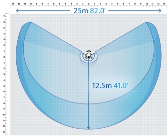
- High-accuracy measurement over a large area
- A wide measurement range up to 15 m (49.2′) can be measured with high accuracy. The WM Series is equipped with the navigation measurement mode, which enables measurement at the same point according to a memorized measurement procedure, allowing anyone to obtain the same measurement data.
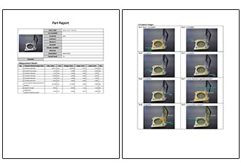
- Inspection reports can be created with photos
- Inspection reports can be automatically created with photos that allow you to understand measurement points at a glance. These inspection reports can not only gain you the trust of your business partners but also allow you to save measurement results as digital data, leading to higher efficiency of in-house data management.
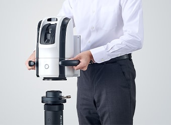
- The portable body can be placed on-site
- The main unit can be carried around on the cart. The WM Series can be brought into worksites and immediately measure the status of the work.
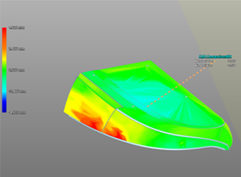
- Check with 3D CAD data
- Comparison measurements are possible between a part being measured and a shape imported from a 3D CAD file. The points of difference between the part and the 3D CAD data can be displayed as a color map. This allows for measurement of free-form curved surfaces and profile tolerances.
The WM Series strongly supports analysis, such as comparison with 3D CAD data, as well as measurement of the dimensions and shapes of the parts of large-scale heat exchangers. It dramatically improves the efficiency of manufacturing of large-scale heat exchangers and of work indispensable for their installation and quality management.
