
Problems and Optimization of In-machine Measurement
In the manufacturing of large-scale products, in-machine measurement is such an important operation that it is seen as the secret weapon for optimization such as improving the quality of cutting and eliminating waste from processes. However, in-machine measurement is performed on machine tools such as five-axis machine tools, five-face milling machines, and lathes, so the time required for measurement directly affects the operating rate. Therefore, the in-machine measurement needs to be performed in as little time as possible.
This section explains the advantages, disadvantages, and measurement points of in-machine measurement performed in the manufacturing processes of large-scale products (which require short delivery times and improved quality) as well as the problems related to these measurements. It also introduces example solutions to measurement problems with our latest coordinate measuring machine (CMM), a device that is vital to optimizing in-machine measurement.
- What Is In-machine Measurement?
- Advantages and Disadvantages of In-machine Measurement
- In-machine Measurement Points
- Problems of In-machine Measurement and Their Solutions
- Optimization of In-machine Measurement

What Is In-machine Measurement?
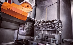
In-machine measurement refers to the measurement of the shapes of a product while it is still on a machine tool. This applies not only to lathes, milling machines, and general machining centers but also to machine tools such as five-axis machine tools and five-face milling machines. Operators measure the product being machined without having to remove it from the tool.
Measuring the dimensions of a product on a machine tool eliminates the work of positioning and aligning the shaft of the product—which must be performed when the product is removed and set back on the tool—and allows for fine adjustments to the accuracy via additional machining.
The international standard ISO 230 prescribes machine tool testing methodology for in-machine measurement such as positioning accuracy tests via numerical control, geometric accuracy tests for the rotation axis, and diagonal positioning accuracy tests.
Advantages and Disadvantages of In-machine Measurement
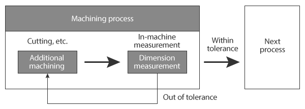
In the normal dimensional inspections of manufacturing processes, the machining accuracy (such as the dimensions of machined products) is measured and products outside of the tolerances are judged as defective. However, during in-machine measurement, the machining accuracy of products being machined is measured on the machine tools during the machining process.
This section introduces the advantages and disadvantages of in-machine measurement obtained by measuring dimensions without removing products from machine tools.
Advantages
Advantages of in-machine measurement include improving the machining quality and eliminating waste from transportation and measurement work. These advantages lead to reduced work times and reduced loads on workers.
Prevents the release of defective products to the next process
With normal measurement, measurements are performed in the inspection process, and then additional machining and similar operations are performed. However, with in-machine measurement, products are measured as they are machined, and then additional processing is performed. The machining accuracy is inspected during the machining process, and then fine adjustments are made to the accuracy with additional processing, preventing the release of defective products to the next process.
Eliminates the waste of transportation
At a manufacturing site, there are seven wastes that should be kept in mind. One of them is the waste of transportation. The waste of transportation refers to unnecessary transportation. In-machine measurement (which measures the dimensions of products on machine tools) eliminates the waste of removing products from machine tools and transporting them to the metrology lab followed by transporting products back to machine tools after measurement. This measurement method also eliminates the waste of time on hand (waiting) that arises from waiting for measuring instruments to become available in the metrology lab.
Eliminates the waste of measurement work
In-machine measurement also eliminates the waste of motion, which indicates the positioning and origin determination required for measurement. In-machine measurement uses the machining origin, so the positioning and origin determination required for measurement are unnecessary, eliminating the corresponding waste of motion.
Disadvantages
Disadvantages include the decreased machine tool operating rate due to dimensional measurement performed on these tools, the load of measurement program creation, and the measurement accuracy.
Decreased machine tool operating rate
If in-machine measurement takes a long time, the machine tool operating rate may decrease. Measurements with hand tools such as calipers, dial gauges, and thickness gauges require multiple workers and require a lot of time and effort if there are many measurement points, so this trend of decreased operating rate becomes clear. Therefore, when performing in-machine measurement, it is necessary to use measuring instruments with good efficiency that can shorten the measurement time as much as possible.
Load of measurement program creation
Recent years have seen the development of machine tools equipped with in-machine measurement functions. However, it is necessary to create programs to perform this measurement.
This task requires dedicated software. Even if the optional functions of 3D CAD software are used, a high level of machining knowledge and programming capability are necessary. Furthermore, new programs must be created to measure new products, so multiple product types being contained in small lots imposes a heavy load on the programmer.
Measurement accuracy
In measurement using in-machine measurement functions of machine tools, errors occur due to factors such as the backlash of the drive unit, which is viewed as a problem. Furthermore, because the drive system of the machine tool itself is used to perform the measurement, it cannot be said that, in the true sense, objective measurement is performed. This is a fundamental problem.
Recent years have seen the development of CMMs that can reduce the above disadvantages, making it easy to obtain the advantages of in-machine measurement.
In-machine Measurement Points
In-machine measurement is performed on various machine tools. This section explains the measurement points to pay attention to during machining with five-face milling machines, vertical lathes, and horizontal boring machines.
Five-face milling machines: positioning and machine allowance

Five-face milling machines are used to machine products that have requirements such as complicated shapes, dimensions of ±0.01 mm (±0.0004″), and strict parallelism and flatness. With these machines, the product remains stationary, and its front, back, left, right, and top surfaces are processed by the moving tool axis connector.
By nature, five-face milling machines are capable of processing with higher accuracy than three-axis machine tools. However, because the tool axis moves in complicated patterns through many processing axes, errors in the product positioning may cause greater processing errors with a five-face milling machine than with a three-axis machine tool.
The machine allowance indicates the part of the material that is cut off. It indicates the part that is removed in excess of the finished dimensions as the part that is cut off when finishing the surface of the material by scraping it, so an understanding of the amount of the machine allowance makes it easy to detect mistakes during machining. If more material is cut off than the machine allowance, the product must be disposed of, so this point must be measured before machining.
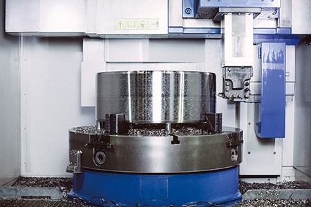
Vertical lathes (turning mills): shaft alignment
Generally, among large-scale lathes, vertical lathes are used to turn especially large products. They are also known as turning mills. The product is set on and turned by a rotating table like a potter’s wheel that has a rotation axis in the vertical direction. The product’s own weight secures it on the rotating table, so large-scale, round products can be rotated stably and machined on the lathe. Also, gravity and centrifugal force lead to less runout than on a horizontal lathe, allowing for high lathe turning accuracy. Vertical lathes can easily be secured to face plates, so they support machining, such as of thin ring products, with high accuracy requirements.
Vertical lathes have these advantages but necessitate shaft alignment because the reference is reset when the product is removed from the chuck. Therefore, when performing additional machining, it is necessary to perform measurements to confirm that shaft alignment to the same position as the previous machining has been completed.
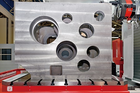
Horizontal boring machines: hole pitch, hole diameter, and position
A horizontal boring machine is a boring machine whose cutting tool has a horizontal rotation axis. It can discharge more chips than vertical boring machines, allowing it to machine larger and deeper holes. Also, the rotation axis of the cutting tool moves to machine the target, so there is no need to move the product, which is suited to the manufacturing of large-scale products.
Horizontal boring machines have these advantages, but the reference is reset when the product is removed from the chuck. Therefore, when performing positioning before machining or when performing additional machining, it is vital to perform measurements to confirm that the product is in the same position and that shaft alignment has been completed.
Problems of In-machine Measurement and Their Solutions
It is important to check the processing status of large-scale products not only after manufacturing but also during manufacturing. Conventionally, these measurements are performed with hand tools such as calipers, dial gauges, and thickness gauges, and it is necessary to transport products to metrology labs to measure three-dimensional shapes. However, measurement, transportation, and setting products on machine tools took a long time, resulting in longer periods before delivery and startup.
To solve these problems, the latest CMMs are used in an increasing number of cases.
KEYENCE’s Wide Area Coordinate Measuring Machine WM Series enables high-accuracy measurement of large-scale products on machine tools with the wireless probe, which makes it suitable for in-machine measurement. Even recessed areas of workpieces can be reached with no movement restrictions within the measurement range, which allows for single-person measurements with the simple operation of touching targets with the probe. Also, unlike hand tools, measurement results do not vary, enabling quantitative measurement.


Positioning and measuring the machining allowance on a five-face milling machine
To use a bridge CMM to measure a large-scale product machined with a five-face milling machine, it is necessary to remove the product from the five-face milling machine and move the product to the metrology lab. This is difficult work that requires many people. Even in-machine measurement with hand tools involves multiple workers and takes an extremely long time, which decreases the operating rate of the five-face milling machine. This is a problem.
Additionally, when these products undergo additional machining while the final accuracy is checked, it is preferable to measure their dimensions on five-face milling machines instead of removing them. Therefore, for dimensional measurement of large-scale products, it can be said that the use of a CMM that is compact, portable, and capable of measuring a large area of a product set on a five-face milling machine is ideal.
The WM Series allows for single-person, 3D measurement of large-scale products without having to remove them from five-face milling machines. The wireless probe makes positioning easy because the reference surface of the product before machining and the machining origin can be measured accurately. Time spent on work before measurements can be significantly reduced.
Also, measuring shapes including the machining allowance before machining is performed and compensating for machining errors improves the efficiency of machining work for fine adjustment at the end of the process. Furthermore, inspection reports with photographs of the measurement points can be created on-site, allowing the accuracy to be guaranteed with high reliability before product delivery.


Measuring the inner diameter, flatness, and perpendicularity of a large-scale flange on a vertical lathe (turning mill)
The positions of bolt holes used to mount support materials and flanges on a pressure vessel are important measurement items that affect strength and stability after installation. Therefore, the inner diameter, flatness, and perpendicularity of the flanges need to be measured not only during manufacturing but also when the pressure vessel is delivered.
When these measurements are performed using hand tools, multiple workers are required. Additionally, some elements of bolts located at the back, such as the center diameter of a bolt hole, cannot be measured due to being blocked by other parts. Even if they can be measured, measured values may be unstable, making it difficult to compare with their designed values.
With the WM Series, it is possible for a single person to perform quantitative measurement by simply touching measurement points with the probe. The wireless probe eliminates movement restrictions, enabling measurement of recessed areas of workpieces. Operators can even measure the inner diameter, flatness, and perpendicularity of a flange by simply touching measurement points with the probe. Even 3D position coordinates can be measured.
Additionally, the WM Series is portable and thus can meet the need to measure 3D work accuracy on-site, which is impossible with ordinary CMMs.


Measuring the hole pitch, hole diameter, and position on a horizontal boring machine
It is necessary to accurately control the pitch, diameter, and position of screw holes used to join flanges (machined with horizontal boring machines) with other parts because the accuracy of these dimensions greatly affects the strength of joints. Operators check the hole pitch and diameter by measuring them with a tape measure or caliper. However, many points need to be measured, so at least two people and a lot of time are required to measure these elements using hand tools. Also, position measurements are difficult to perform with hand tools because it is necessary to measure the distance from the datum. To measure with a bridge CMM, it is necessary to remove the product from the horizontal boring machine and move the product to the metrology lab. This is difficult work that requires many people. Furthermore, positioning and other settings are required when placing the product back on the horizontal boring machine for additional machining.
The WM Series makes it easy to determine the hole pitch, diameter, and position by simply touching the wireless probe against the surfaces to measure. There is no need to remove the product from the horizontal boring machine. What’s more, 3D elements, such as diagonal dimensions and plane angles, can also be measured in addition to simple linear distances. The WM Series also enables comparison measurement of measurement targets and shapes imported from a 3D CAD file and outputting of the measurement results as CAD data.


Optimization of In-machine Measurement
The WM Series enables in-machine measurement on various machine tools with the simple operation of touching targets with the wireless probe. In addition to the features introduced above, the WM Series has the following advantages.

- High-accuracy measurement over a large area
- A wide measurement range up to 15 m (49.2′) can be measured with high accuracy. The WM Series is equipped with the navigation measurement mode, which enables measurement at the same point according to a memorized measurement procedure, allowing anyone to obtain the same measurement data.

- Augmented reality measurement guidance
- Image data from measured targets can be saved as a measurement procedure. These procedures can be used for OK/NG judgment when measuring multiple targets of the same shape simply by following the on-screen instructions and touching the probe to the target.

- Statistical analysis function for summarizing data
- Measurement results from guided measurement will be automatically saved to the hard disk drive. Saved data can then be extracted for use with various statistic analyses such as checks of the statistical values, trend graphs, and histograms.

- Easy-to-understand interface
- CMM interfaces are often a mess of complex and unfamiliar commands. The WM Series provides intuitive operation using images and icons, so anyone can easily understand how to operate the system.
The WM Series strongly supports analysis, such as comparison with 3D CAD data, as well as measurement of the dimensions and shapes of parts during in-machine measurement. It dramatically improves the efficiency of manufacturing of various machined parts and of work indispensable for their setup and quality management.
