
Optimization of Industrial Equipment Leveling
Many types of industrial equipment, such as machine tools, food processing machines, and semiconductor manufacturing devices, are installed horizontally. This is because industrial equipment is designed to function as expected when installed horizontally. Horizontal reference planes are used even when industrial equipment is installed at an angle. Levelling is an important part of installing equipment horizontally. Even small errors in levelling can cause defective products or decrease the service life of equipment and tools, especially when industrial equipment is large.
Based on levels of industrial equipment, this section explains basic knowledge, such as measuring instruments used for leveling and the necessity of level measurement, points and problems of dimensional measurement which is the most important work for leveling, and solutions to these problems.
- What Does Level Mean?
- Measuring Instruments Used for Leveling
- Necessity of Leveling
- Measurement for Leveling
- Problems of Leveling and Their Solutions
- Optimization of Industrial Equipment Leveling

What Does Level Mean?
Level is a measure of how horizontal something is. For industrial equipment, accurate leveling is fundamental and essential to maintaining operation accuracy. Many types of industrial equipment are fixed to the floors of facilities with bolts during use, and they are installed horizontally by checking the height and angle while tightening and loosening these bolts. This work is called leveling. While industrial equipment is used, its levels change due to various factors, such as its own weight, vibration, and heat. Leveling needs to be performed periodically even after installation.
Measuring Instruments Used for Leveling
This section introduces typical measuring instruments used for leveling. Various measuring instruments are used for leveling according to the elements to be measured, required measurement accuracy, target sizes, and other conditions. Level is usually measured using multiple types of measuring instruments and high levels of measurement technique and a lot of work are required.
Level
Levels are instruments that measure whether planes and lines are horizontal, vertical, or at 45 degrees. Various types of levels are available, such as spirit levels, digital spirit levels, and bull’s eye levels.
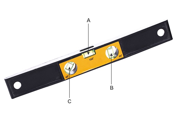
- A
- Horizontal bubble tube
- B
- Vertical bubble tube
- C
- 45° bubble tube
- Spirit level
- A glass vial filled with a liquid, called a bubble tube, is incorporated into part of a frame. The frame is placed on a target surface to determine whether the surface is horizontal according to the bubble position in the bubble tube. Some spirit levels can measure vertical planes and lines and angles such as 45 degrees.
- Digital spirit level
- In addition to bubble tubes, digital spirit levels are equipped with a monitor that digitally indicates the reading. Precise values of various angles can be read in addition to vertical and horizontal planes and lines.
- Bull’s eye level
-
This measuring instrument is used to check large horizontal planes. An inclination in any direction can be measured, but the measurement is not very accurate.
In addition to the levels introduced above, there are many other types of levels, such as angle levels for measuring inclination angles and gradients with accuracy, levels with a built-in laser pointer, and levels with built-in tape measures.
Dial gauge

Dial gauges are measuring instruments used by installing them on a measurement jig called a stand or a precision device. There are two types of dial gauges: spindle and lever.
Spindle types are suitable for measuring targets with large dimensional variations, while lever types are capable of measuring narrow spaces that cannot be measured with spindle-type dial gauges.
When used for leveling, dial gauges are installed on a reference plane and moved to measure the parallelism to a target. Dial gauges are used in many manufacturing sites because they are highly versatile and their measurement values are highly reliable.
Laser level

Laser levels are measuring instruments that emit laser beams to a target to project a horizontal reference line, vertical reference line, and other reference lines. In architectural terms, reference lines are called black ink lines and work that draws black ink lines is called black ink marking. This instrument is called a laser black ink marker because it draws reference lines using laser beams.
Laser levels are used for the installation of industrial equipment because they can project reference lines and set accurate positions without using spirit levels or dial gauges.
Necessity of Leveling
Leveling is fundamental to the installation of any type of industrial equipment and needs to be performed as part of every installation process.
For example, if metal casting molds are tilted, it may adversely affect materials poured into the molds and cause defects such as deformation and warpage. Tilted cutting machines and pressing machines may place loads on unexpected areas, causing machining to not be performed properly or machines to break down.
Tilted material handling equipment, such as conveyors and transfer robots, may cause inappropriate conveyance such as catching of conveyed items or other problems such as damage to conveyed items.
If parts are mounted on a base frame that has not been leveled, their mounting positions cannot be measured with accuracy. When industrial equipment needs to be reinstalled in a different location, its original state is restored based on levels.
As explained above, inaccurate leveling can have various adverse effects. It is necessary to strictly measure levels when industrial equipment, stands, and base frames are manufactured and installed.
Measurement for Leveling
Dimensional accuracy for leveling greatly affects the performance and durability of industrial equipment. Low dimensional accuracy may cause defective machining of machine tools, inappropriate conveyance of material handling equipment, and low parts mounting accuracy on stands and base frames. To avoid these problems when installing industrial equipment, it is necessary to measure levels and confirm that they are within the necessary tolerances.
Measurement points
Various measurement elements are used for leveling. This section explains three of them: alignment adjustment, level adjustment, and strain measurement.
Alignment adjustment
Alignment adjustment including shaft centering and target positioning are essential parts of factory automation (FA).
Alignment needs to be adjusted while equipment is assembled on an assembly surface plate. Alignment is adjusted while the equipment is at room temperature. However, mechanical torque during operation, stress from vibration, and heat expansion occur while the equipment is in operation. Before alignment adjustment, these elements need to be taken into account to understand the differences between alignment when the equipment is at room temperature and when it is running.
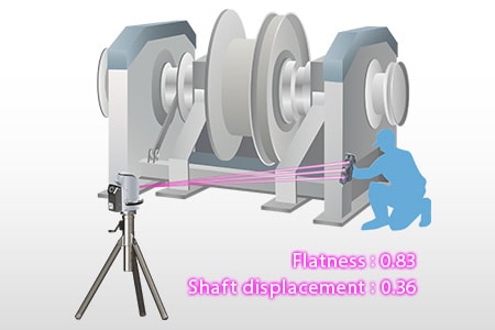
To perform alignment adjustment, levels are fundamental. Low leveling accuracy may increase vibration during operation, decrease the service lives of bearings, and at worst, damage parts such as couplings.
Level adjustment
Level adjustment is a vital part of installation of equipment stands and base frames. Floor level measurement and path line adjustment are especially important for conveyance equipment that transports items between pieces of equipment.
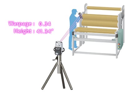
Floor level measurement detects height differences of the floors on which devices are installed and path lines are the heights at which items are conveyed. Typical equipment is designed with floor levels taken into account. When it is installed, levels are finely measured, with leveling plates added or adjusting bolts turned to make it horizontal. Then, the levels of the conveying equipment are adjusted to the path lines.
In this way, level adjustment is performed while the levels of installation floors and installed equipment are measured and adjusted, which takes a long time in many cases.
Strain measurement
After the installation of industrial equipment, its levels may change and its equipment stands or base frames may be put under strain due to various factors that occur during processing, such as heat, vibration, and workpiece weight load. Industrial equipment on a strained equipment stand or base frame may fail to function as designed, increasing the number of defective products or decreasing its service life. In many cases, various devices and units are installed based on parallelism or perpendicularity to their base frames, and thus cannot be installed at accurate heights and angles when the installation surfaces of the base frames are strained. It is essential to measure the dimensions to determine the strain of equipment stands and base frames, the flatness of parts and unit installation surfaces, and other related elements during maintenance after installation.
Problems of Leveling and Their Solutions
Leveling needs to be performed during both manufacturing and installation of industrial equipment, equipment stands, and base frames. These measurements are usually performed using levels, dial gauges, laser levels, and tape measures. Many equipment stands and base frames are large, so they inevitably require two to three people to measure. There are also problems with variations in measured values between operators, difficulty understanding strain tendencies, and long measurement times.
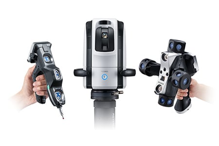
To solve these problems, the latest CMMs are used in an increasing number of cases. KEYENCE’s Wide Area Coordinate Measuring Machine WM Series enables high-accuracy dimensional measurement of installed equipment with its wireless probe. Even recessed areas of workpieces can be reached with no movement restrictions within the measurement range, which allows for easy single-person measurement with the simple operation of touching targets with the probe. Unlike measurements using measuring instruments such as levels, dial gauges, and laser levels, results do not vary, enabling quantitative measurement.

Alignment adjustment for manufacturing and processing equipment
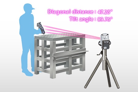
When the alignment of manufacturing or processing equipment is adjusted, the left, right, top, and bottom assembly positions are aligned on an assembly surface plate while deviations are measured with measuring instruments such as dial gauges and laser levels.
Measurement using dial gauges or laser levels requires at least two workers. It is difficult to perform accurate measurement because measured values tend to vary each time a measurement is performed. When a dial gauge is used, the measured values vary according to the angle and strength at which it is applied to the target, which causes variations in measured values among operators. To achieve sufficient measurement accuracy, it is also necessary to repeat measurements on a specified axial line, which can take days of work.
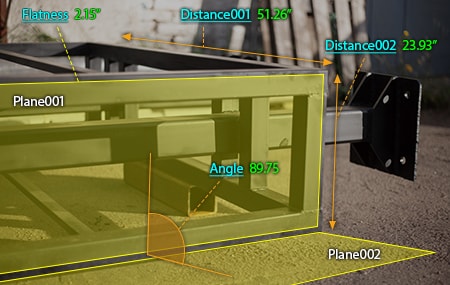
The WM Series enables measurement by simply touching measurement points with the probe. Parallelism, height, and distances between parts can also be measured by simply touching the reference element and a target element with the probe. This enables quick single-person measurement without variations in measured values among operators.
Additionally, the WM Series is portable and thus can meet the need to measure 3D installation accuracy on-site, which is impossible with ordinary CMMs.
Level adjustment of manufacturing and processing equipment stands and base frames
Typical equipment stands are manufactured using square pipes with thick walls and the base frame installation areas are processed with a machining center to be flat, usually within tolerances of 0.1 mm (0.0039″) or less, to achieve the necessary accuracy.
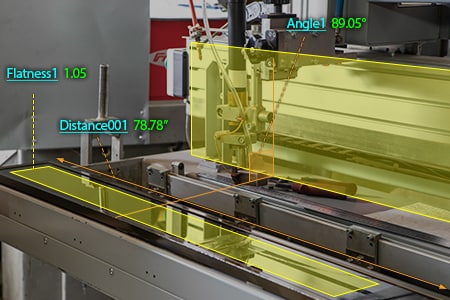
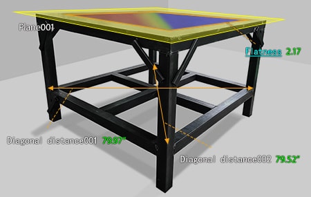
To obtain flatness, at least three points are measured on a target plane using levels or dial gauges and the maximum deviation is calculated as the flatness, or gaps generated when a target plane is placed between two parallel planes are measured using measuring instruments, such as feeler gauges, and OK/NG judgment is performed. However, it is impossible to accurately measure and quantify the flatness of 3D shapes, such as warpage and curvature.
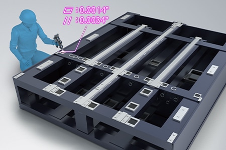
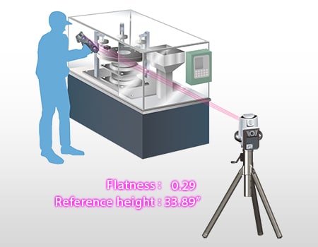
KEYENCE’s Wide Area Coordinate Measuring Machine WM Series enables accurate flatness measurement by simply touching a target plane with the wireless probe. It can also visualize warpage and curvature of an entire surface in a color map, significantly improving efficiency of work that processes targets into intended shapes to complete them. Various other elements—such as perpendicularity, position, and parallelism—can also be measured. The WM Series greatly contributes to a higher quality of manufacturing and installation of equipment stands and base frames.
Strain measurement and drawing creation for manufacturing and processing equipment
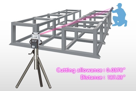
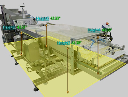
Changes in levels and strain of equipment stands and base frames caused during operation are measured as part of maintenance of installed manufacturing and processing equipment.
Levels are commonly checked by measuring distances from the floor level to reference positions on equipment using tape measures or levels, and strain is often measured by tracing target surfaces with dial gauges. However, many component parts are large, inevitably requiring two to three people to measure each of them. There are also problems with variations in measured values between operators, difficulty understanding strain tendencies, and long measurement times. Another problem is that analog tools such as hand tools cannot directly measure dimensions when they are specified from the equipment center in drawings.
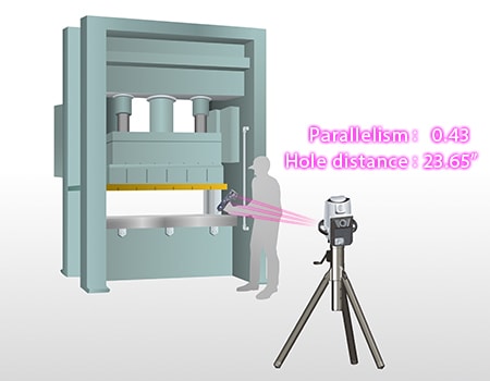
KEYENCE’s Wide Area Coordinate Measuring Machine WM Series enables high-accuracy measurement of levels and strain with the wireless probe. Unlike measurements using measuring instruments such as tape measures, levels, and dial gauges, results do not vary, enabling quantitative measurement.
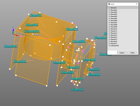
Dimensions can also be measured in three dimensions without considering the floor level, and measured elements can be exported as a STEP/IGES file. This makes it possible to create 3D CAD data from the measurement results of an actual product. 3D CAD data can be used to create drawings of existing equipment. Additionally, the WM Series is portable, so it can be brought to maintenance sites for measurement.
Optimization of Industrial Equipment Leveling
The WM Series enables single-person measurement of industrial equipment levels with the simple operation of touching targets with the wireless probe. In addition to the features introduced above, the WM Series has the following advantages.
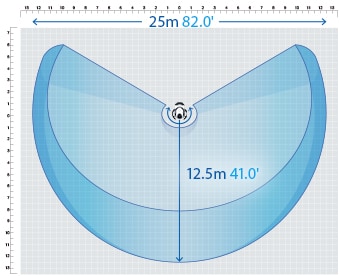
- High-accuracy measurement over a large area
- A wide measurement range up to 15 m (49.2′) can be measured with high accuracy. The WM Series is equipped with a navigation measurement mode, which enables measurement at the same point according to a memorized measurement procedure, allowing anyone to obtain the same measurement data.
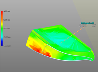
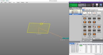
- Check with 3D CAD data
- Comparison measurements are possible between a part being measured and a shape imported from a 3D CAD file. The points of difference between the part and the 3D CAD data can be displayed as a color map. This allows for measurement of free-form curved surfaces and profile tolerances.
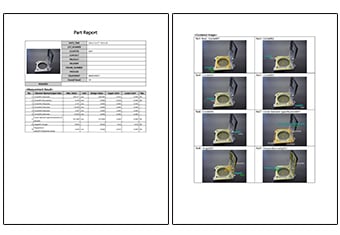
- Inspection reports can be created with photos
- Inspection reports can be automatically created with photos that allow you to understand measurement points at a glance. These inspection reports can not only gain you the trust of your business partners but also allow you to save measurement results as digital data, leading to higher efficiency of in-house data management.
- Easy-to-understand interface
- CMM interfaces are often a mess of complex and unfamiliar commands. The WM Series provides intuitive operation using images and icons, so anyone can easily understand how to operate the system.
The WM Series strongly supports analysis, such as comparison with 3D CAD data, as well as measurement of industrial equipment levels. It dramatically improves the efficiency of manufacturing of industrial equipment and of work indispensable for its installation and quality management.
