
Optimization of Dimensional Measurement of Pile Drivers and Steel Pipe Piles
In recent years, large-scale disasters that used to happen only once every few decades have been happening frequently. In light of damage from these disasters, awareness of disaster prevention is growing nationwide. As damage from earthquakes and typhoons is particularly severe, the national resilience plan released by the government urges the enhancement and accuracy improvement of groundwork for building foundations.
Dimensional accuracy of piles, key parts of groundwork, and pile drivers used for construction greatly affect performance. Additionally, more efficient manufacturing is urgent in response to an increasing number of construction cases.
This section focuses on dimensional measurement of pile drivers and piles and introduces basic knowledge of mechanisms and piling methods of pile drivers, problems of conventional measurement methods and their solutions.
- What Is a Pile Driver?
- Structures of Pile Drivers and Piles
- Necessity of Dimensional Measurement of Pile Drivers and Piles
- Dimensional Measurement of Pile Drivers and Piles
- Problems of Pile Driver and Pile Dimensional Measurement and Their Solutions
- Optimization of Dimensional Measurement of Pile Drivers and Steel Pipe Piles

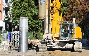
What s a Pile Driver?
A pile driver, also known as a piler, is a construction machine that drives piles into soil for building groundwork. There are various pile driving methods including hammer striking, pressing, and drilling, as well as methods that combine hammers and pressing. Pile driving by pressing is called the press-in method, and a typical example is the all casing method*. The press-in method does not cause construction pollution such as vibration and noise, so it is used at various construction sites. Pile drivers using hammers or drills also have options that can be applied in consideration of the surrounding environment, such as being equipped with noise reducers.
- All casing method:
- In this method, steel pipe piles called casing tubes are rotated and pushed into the entire length of a drilled hole and protect the hole wall during drilling. Earth and sand accumulated by drilling in casing tubes are removed with tools, such as hammer grabs, and concrete is poured into the created hole.
Structures of Pile Drivers and Piles
There are three types of pile drivers, as listed below.
- Hammer strike
- Piles are driven into soil by striking or vibrating the pile with a large striking hammer.
- Press-in
- Piles are driven in hydraulically using their own weight.
- Drill
- Piles are driven into soil by drilling the ground with a screw type drill, such as an auger drill.
Pile types include steel pipe piles and H-beams. This section explains the structures of hydraulic pile drivers, a typical type of pile driver, and steel pipe piles.
Hydraulic pile driver (hydraulic pile hammer)
Hydraulic pile drivers, also known as hydraulic pile hammers, strike the pile with a ram that is pushed down and accelerated with a force of a hydraulic hammer. Compared to pile drivers that use only the gravity of the ram, the length of the hammer can be reduced. Additionally, the amount the pile is driven per strike is larger and the strike motion can be repeated many times, which can reduce construction periods.
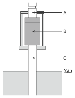
- A
- Hydraulic hammer
- B
- Ram
- C
- Steel pipe pile
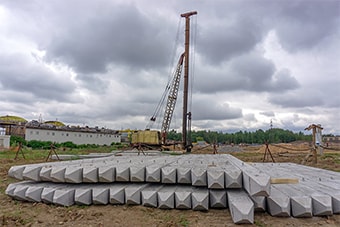
Steel pipe pile
Steel pipe piles are manufactured with SKK400 or SKK490 steel. To dig into the ground, pile tips are equipped with hard blades that can dig through hard objects, such as boulders and bedrock, and piles need to have precise cylindrical shapes.
For example, a casing tube, which is a steel pipe pile used for the all casing method, is equipped with a first tube at the end facing the digging direction, and the tip of the first tube is equipped with blades. To accurately dig into deep layers vertically, casing tubes have a precise cylindrical shape and the cutting edge at the first tube end is equipped with superhard bits made from tungsten carbide or other hard materials to crush boulders and bedrock.
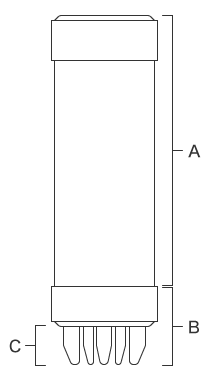
- A
- Casing tube
- B
- First tube
- C
- Cutting edge
Necessity of Dimensional Measurement of Pile Drivers and Piles
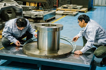
Pile driver parts are manufactured at plate working plants. The materials of many parts go through machining processes, such as cutting and welding, with robots or automatic equipment but fine parts are manually processed by experienced workers. After the above processes, parts are further machined with five-face machining centers or similar equipment and then assembled. Pile driver manufacturing consists of many processes, so part dimensions may change due to various factors such as heat in welding processes or machining pressure in cutting processes.
The dimensional accuracy of piles greatly affects pile driving accuracy. For example, steel pipe piles are manufactured by forming rolled steel plates into a tubular shape and welding the edges together. The dimensions may change due to defective forming during rolling or heat during welding. If defective piles are found at construction sites, it can cause serious issues up to suspension of construction, because pile deformation not only affects pile driving accuracy but also building strength.
For this reason, dimensional measurement and inspection of pile drivers and piles during manufacturing processes is essential for smooth construction of groundwork for strong foundations.
Dimensional Measurement of Pile Drivers and Piles
Pile drivers accurately drive piles into soil vertically. As they drive piles with lengths of several meters into the ground, even slight a misalignment or inclination of a pile driver can result in large errors on higher floors of buildings. This also applies to piles. Additionally, misaligned or tilted piles can also damage the pile tip and decrease the overall strength.
Dimensional measurement points
This section explains dimensional measurement points of pile drivers and casing tubes.
Pile driver
The dimensions of the rails on a pile driver that hold the pile clamped with a chuck are measured. Specifically, the parallelism of vertical chuck rails, the hole pitch of guide pipes, and the bolt hole pitch on the guide roller support frame mounted on the guide roller mounting frame need to be measured.
Casing tube
For the steel pipe piles used for the all casing method, warpage, plane-to-plane distances, and angles of casing tubes are measured. The dimensions of casing tubes, first tubes, and cutting edges are strictly measured to check whether they have been accurately assembled without warpage.
Problems of Pile Driver and Pile Dimensional Measurement and Their Solutions
It is important to measure the dimensions of pile drivers and piles not only after manufacturing but also during each process. The dimensions of parts are usually measured using hand tools, such as tape measures and leveling strings, and their three-dimensional shapes and GD&T are measured using bridge or arm coordinate measuring machines (CMMs).
These methods present several issues, such as the low accuracy of hand tools and the time it takes to transport targets and set them on bridge and arm CMMs, which can cause delays in delivery or construction. To solve these problems, the latest CMMs are used in an increasing number of cases.
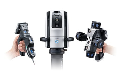
KEYENCE’s Wide Area Coordinate Measuring Machine WM Series can reach even recessed areas of workpieces with no movement restrictions within the measurement range and dimensions can be measured with the simple operation of touching target points with the probe held in a single hand. Unlike measurements using hand tools such as tape measures, leveling strings, and dial gauges, results do not vary, enabling quantitative measurement. Additionally, measurements can be performed when and where you want by eliminating the need to move workpieces to be measured.

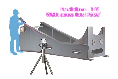
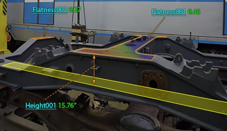
Parallelism measurement of vertical chuck rails on pile drivers
The closer the pile driver rails are to a pile, the smaller vibration, allowing the chuck to move smoothly. If the rail dimensions are inaccurate and parts are positioned closer to the pile, friction is generated between the parts and pile, preventing the pile from moving smoothly. Additionally, if the rails holding the ram are not accurately parallel to each other, the ram will not move appropriately and will fail to apply sufficient force to the pile.
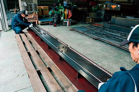
The parallelism of rails is measured by tracing them with dial gauges or by measuring the gaps between the surface plate and rails using feeler gauges. The rails are long, so it takes multiple people to measure them. Additionally, the measured values vary according to the angle and strength at which various operators apply dial or feeler gauges to the target.Three-dimensional distances and coordinates are measured using bridge or arm CMMs. However, workpieces need to be transported to a measuring room when bridge CMMs are used and measurement takes time when arm CMMs are used due to their small measurement range.
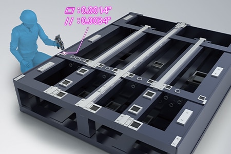
The WM Series can perform rail parallelism measurement even after installation by simply touching measurement points with the probe. This enables quick single-person measurement without variations in measured values among operators even when they are unfamiliar with measurement work.
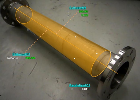
Even 3D distances and coordinates can be directly measured, with a wide measurement range up to 15 m (49.2′) can be measured with high accuracy. Additionally, the WM Series is portable and thus can meet the need to measure 3D installation accuracy on-site and measure dimensions on machine tools, which are impossible with ordinary CMMs.
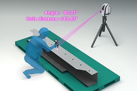
Measurements of warpage, plane-to-plane distances, and angles of casing tubes
Warpage of casing tubes is measured by tracing with dial gauges or by measuring gaps using leveling strings. Plane-to-plane distances are measured with tape measures and plane angles are measured with angle meters. However, the lengths of casing tubes used for foundations of large-scale buildings is several meters, increasing the tendency for measured values to vary among operators when they are measured with hand tools. The curved surfaces of casing tubes are measured using bridge or arm CMMs. Neither measuring instrument can measure curved surfaces efficiently because casing tubes need to be transported to a measuring room for measurement with a bridge CMM and the measurement range of an arm CMM is small.
The WM Series is designed to be portable and to be set anywhere, eliminating the need to move targets. This measuring instrument can be set close to a target, which enables measurement to be started immediately.
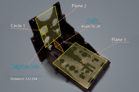
Unlike tracing measurement in which targets need to be moved, warpage can be measured by simply touching the reference element and target element points with the probe. The dimensions of each part, such as plane-to-plane distances and angles, can also be measured easily.
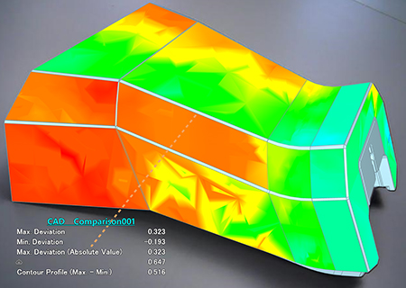
It is possible to compare measurement data and shapes imported from 3D CAD files. Differences from CAD drawings can be checked at measurement sites. The points of difference between the part and 3D CAD data can be displayed as a color map, which enables visual checking of differences.
Optimization of Dimensional Measurement of Pile Drivers and Steel Pipe Piles
The WM Series enables single-person measurement of long workpieces, such as pile drivers and piles, with the simple operation of touching with the wireless probe. In addition to the features introduced above, the WM Series has the following advantages.
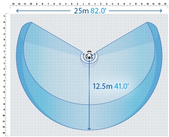
- High-accuracy measurement over a large area
- A wide measurement range up to 15 m (49.2′) can be measured with high accuracy. The WM Series is equipped with a navigation measurement mode, which enables measurement at the same point according to a memorized measurement procedure, allowing anyone to obtain the same measurement data.
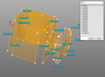
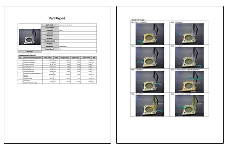
- Measurement results can be output as 3D models
- The measured elements can be exported as a STEP/IGES file. 3D CAD data can be created on the basis of the measurement results of an actual product even if no drawing is available.
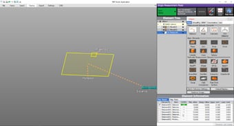
- Easy-to-understand interface
- CMM interfaces are often a mess of complex and unfamiliar commands. The WM Series provides intuitive operation using images and icons, so anyone can easily understand how to operate the system.
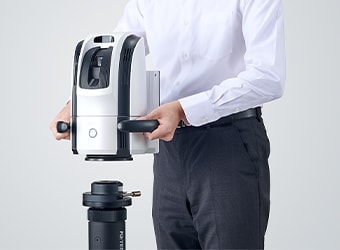
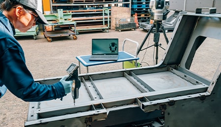
- The portable body can be placed on-site
- The main unit can be carried around on the cart. The WM Series can be brought into worksites and immediately measure the status of work.
The WM Series strongly supports analysis, such as comparison with 3D CAD data, as well as dimensional measurement of pile drivers and piles. It dramatically improves the efficiency of manufacturing of pile drivers and piles and of work indispensable for their construction and maintenance.
