
Dimensional Measurement of Pressure Vessels
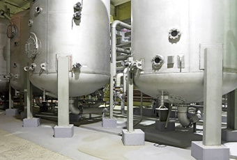
Pressure vessels have evolved since the invention of boilers and spread to use in many plants on the back of technological innovation. Pressure vessels are hermetic containers that are essential components in many plants, such as chemical plants, oil plants, and power plants.
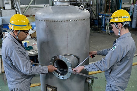
The pressure vessels used in these facilities are large. This not only makes it difficult to measure their dimensions accurately and also requires more than one person for measurement, resulting in a lot of labor and time spent. Improvement of measurement efficiency for safety management is an urgent issue, while there is also a growing demand for higher measurement accuracy.
This section explains basic knowledge of pressure vessels such as their structure, the necessity of dimensional measurement, and measurement methods. It also introduces problems with conventional measurement methods and their solutions.
- What Is a Pressure Vessel?
- Pressure Vessel Structure
- Necessity of Dimensional Measurement of Pressure Vessels
- Dimensional Measurement of Pressure Vessels
- Problems of Dimensional Measurement of Pressure Vessels and Their Solutions
- Optimization of Dimensional Measurement of Pressure Vessels

What Is a Pressure Vessel?
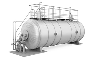
Pressure vessels are hermetic containers that receive internal or external pressure. Pressure vessels are installed in plants, such as oil plants, chemical plants, and power plants, and are frequently used to distill, separate, and react raw material liquids to manufacture products or contain steam.
As the pressure in a vessel is higher or lower than the ambient pressure, strict dimensional accuracy is required during manufacturing.
Pressure Vessel Structure
There are many types of pressure vessels and they all consist of many parts. This section explains parts commonly used in many pressure vessels.
A pressure vessel body consists of a shell and heads. The shell is equipped with flanged nozzles to which valves are installed, legs that fix the pressure vessel, and other parts. These parts can be broadly divided into two types: pressure retaining parts and non-pressure retaining parts. Pressure retaining parts are used in locations exposed to external or internal pressure. Shells, heads, nozzles, and some other parts are pressure retaining parts. If these parts are damaged, internal gases or liquids may leak and air may enter the vessel. Therefore, high strength and high machining accuracy are required.
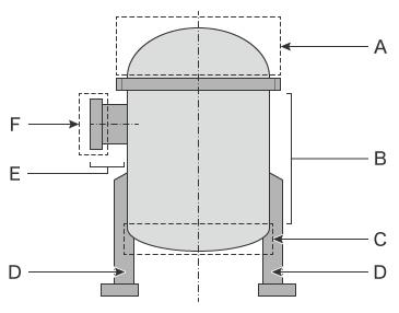
- A
- Head (upper head)
- B
- Shell
- C
- Head (lower head)
- D
- Leg
- E
- Nozzle
- F
- Flange
Shell
This is the main part of a pressure vessel. A shell is a cylindrical shape because this shape has the most stable resistance against pressure applied and low manufacturing costs. In addition to cylindrical shells, conical shells also see use. Conical shells are used when the shell dimeter needs to be changed.
Head
A head is a hemispherical part mainly used at the ends of a pressure vessel. Its cross-section may be dish-shaped, semi-elliptical, hemispherical, or conical. Semi-elliptical or hemispherical heads are used for high-pressure vessels and dish-shaped or conical heads are used for low-pressure vessels. Spherical pressure vessels with no shell are called spherical shells.
Necessity of Dimensional Measurement of Pressure Vessels
Pressure vessels are used for various equipment, such as shell and tube heat exchangers, reactors, atmospheric distillation columns, and nuclear reactors. In the past, many serious accidents occurred with this type of equipment due to explosions of pressure vessels. It is important to strictly inspect their dimensions to prevent the same accidents from reoccurring. Shells and heads, pressure retaining parts that receive high internal or external pressure, need to be strictly inspected in terms of dimensions, flatness, circularity, screw hole positions, and flanged nozzle installation angle, especially when they are used for large pressure vessels.
Measurement of flatness, circularity, and position
Measurement includes various elements such as dimensions and shapes. This section explains how to perform measurements and calculate flatness, circularity, and positions. Flatness is a measure of surface irregularities from a reference plane. Circularity is a measure of how close an object is to a perfect circle. Position is an index of how accurately a point is located based on reference planes or lines. These measurement items are collectively called GD&T.
Circularity is used to control the accuracy of the shells and heads that make up pressure vessel bodies and of finished pressure vessels after assembly. Flatness and position are often used to check the accuracy of each nozzle and flange before installation and of their installation on pressure vessel bodies. These elements can be calculated by inputting values measured using hand tools or other measuring instruments into a calculation tool such as spreadsheet software or calculation websites. Using a dedicated measuring instrument for each measurement item or the latest coordinate measuring machines (CMM) makes it possible to measure GD&T items directly.
Flatness
There are two types of flatness: flatness based on maximum deviation and flatness based on maximum inclination.
Flatness based on the maximum deviation is obtained by setting a plane that passes through three points that are as far away as possible from the target plane. The maximum difference from the design drawing at one of the specified points is considered the flatness.
Flatness based on the maximum inclination is obtained by placing a target plane between parallel planes and measuring the gaps created.
Circularity
Two-point measurement is performed on the outer form divided into four or eight sections. Circularity is the value obtained by dividing the difference between the maximum and minimum values by two. Circularity measurement accuracy for cylindrical objects can be increased by measuring more points.
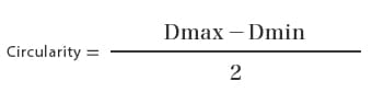
- Dmax
- Maximum value
- Dmin
- Minimum value
Position
The position requirement specifies the accuracy of the position in relation to the datum (reference plane or line). A position is a deviation measured in the X- and Y-axis directions. The measured value on each axis is subtracted from the value on the drawing to obtain the deviation. The position is obtained by multiplying the square root of the sum of two deviations squared by two.
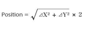
- ⊿X
- Deviation in the X-axis direction
- ⊿Y
- Deviation in the Y-axis direction
Dimensional Measurement of Pressure Vessels
Dimensional inaccuracies of shells and heads can cause engagement failures of welded joints and greatly affect their sealing performance and airtightness. Vessel bodies and flanges assembled by welding are often not completed as specified in drawings because welded sections are deformed by heat. Therefore, the dimensions of finished pressure vessels need to be measured to confirm that deformation is within tolerances.
Dimensional measurement points
Major points to check and their tolerances are as follows:
Vessel body (shell and head)
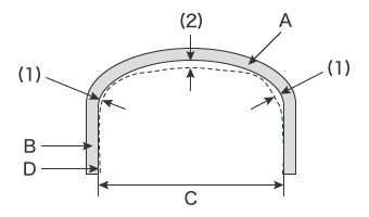
- A
- Head
- B
- Shell
- C
- Inner diameter
- D
- Designed dimensions
- Shell straightness
- Up to 6 mm (0.2362″) for a length of 6 m (19.7′), up to 20 mm (0.7874″) for the total length
- Shell circularity
- The difference between the maximum and minimum values of the internal diameter of a cross-section is up to 1%.
(Up to ±0.5% of the internal diameter specified in a drawing) - Head shape
- Gap (1) and gap (2) shown in the figure on the right are respectively up to ±1.25% of the internal diameter.
Total length: Up to ±1.5 mm (0.0591″) for a length of 1 m (3.3′)
Nozzle (including flange)
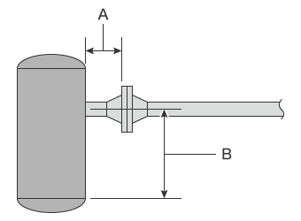
- A: Nozzle height
- Up to ±5 mm (0.1969″)
- B: Nozzle installation position
- Up to ±10 mm (0.3937″) from the reference line
Problems of Dimensional Measurement of Pressure Vessels and Their Solutions
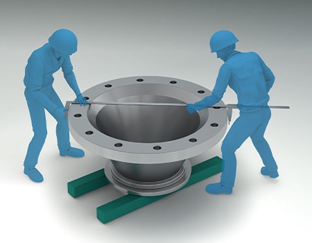
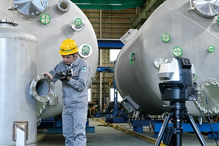
It is important to confirm not only the dimensional accuracy of a finished pressure vessel but also machining accuracy during manufacturing and installation accuracy during parts replacement. Conventionally, these measurements are performed using tape measures, calipers, and similar tools. Many component parts are large, inevitably requiring two to three people to measure each of them. There are also problems with variations in measured values between operators, difficulty understanding strain tendencies, and long measurement times. Another problem is that analog tools such as hand tools cannot directly measure dimensions when they are specified from the center of a tank or flange in drawings.
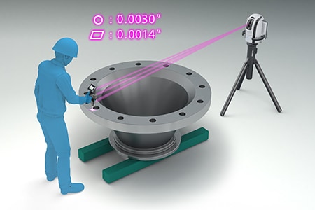
To solve these problems, the latest CMMs are used in an increasing number of cases. KEYENCE’s Wide Area Coordinate Measuring Machine WM Series enables for high-accuracy dimensional measurement of pressure vessels with the wireless probe. Even recessed areas of workpieces can be reached with no movement restrictions within the measurement range, which allows for easy single-person measurement with the simple operation of touching targets with the probe. Unlike measurements using measuring instruments such as dial gauges, tape measures, and calipers, results do not vary, enabling quantitative measurement. Additionally, dimensions can be measured directly in three dimensions based on reference virtual lines, which ensures the dimensions specified in drawings can be measured with high reliability.

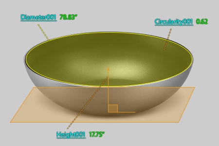
Measurement of head diameter, circularity, and other elements
Pressure vessels used in boiling water reactors (BWR) with a power generating capability of 1.1 million kW have a height of approximately 22 m (72.2′) and a width of approximately 6 m (19.7′) (internal diameter). Heads mounted on pressure vessels of this size are measured in terms of the diameter, circularity, radius of a hemisphere, distance from the hemispherical top to the end face, and other related elements. Measurement using calipers or tape measures requires at least two workers and it is difficult to perform accurate measurement because measured values vary every time measurement is performed. For example, circularity is checked by measuring the distances between two points using tape measures. However, measured values vary according to the angle and strength at which the tape measure is applied to the target, which causes variations in measured values among operators. Additionally, to achieve sufficient measurement accuracy, it is necessary to repeat measurements on a specified axial line, which can take days of work.
The WM Series enables measurement by simply touching measurement points with the probe. Circularity, hemispherical radius, and distances between parts can also be measured by simply touching the reference element and a target element on the head with the probe. This enables quick single-person measurement without variations in measured values among operators. Additionally, deviations from designed tolerances can be judged instantaneously.
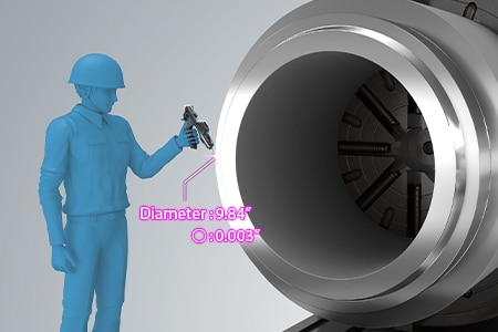
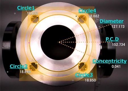
Bolt hole position measurement
The positions of bolt holes used to mount support materials and nozzles on a pressure vessel are important measurement items that affect strength and stability after installation. The bolt hole positions, such as height from the bottom of the pressure vessel and hole intervals, need to be measured not only during manufacturing but also when the pressure vessel is delivered. Bolt holes are measured using position coordinates along with the flatness and angle of joint surfaces. When these measurements are performed using hand tools, multiple workers are required. Additionally, some elements of bolts located at the back, such as the center diameter of a bolt hole, cannot be measured due to being blocked by other parts. Even if they can be measured, measured values may be unstable, making it difficult to compare with their designed values.
With the WM Series, it is possible for a single person to perform quantitative measurement by simply touching measurement points with the probe. The wireless probe eliminates movement restrictions, enabling measurement of recessed areas of workpieces. Even the installation surface angles of support parts and nozzles can be measured by simply touching measurement points with the probe. Even 3D position coordinates can be measured. Additionally, the WM Series is portable and thus can meet the need to measure 3D work accuracy on-site, which is impossible with ordinary CMMs.
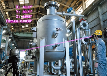
Flange installation angle measurement
The position of a flange welded on a large pressure vessel is checked by measuring the distance from the center of the pressure vessel shell. The measurement distance is several meters, so their positions are measured using tape measures or calipers. The installation angle and flatness are measured using other measuring instruments, such as levels and calipers. However, measured values obtained with these hand tools vary according to the angle, strength, and position at which the tools are applied to the target, which causes variations in measured values among operators.
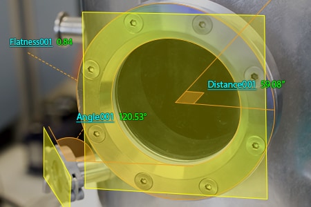
With the WM Series, it is possible for a single person to perform quantitative measurement with no variations by simply touching measurement points with the probe. The angle of installed flanges can also be measured by simply touching with the probe. Even 3D position coordinates can be measured. GD&T, such as position and flatness, can also be measured with accuracy. This enables measurement of important dimensions, which were measured using conventional measuring instruments, while intuitively checking measurement points on the monitor.
Also, flatness can be displayed with easy-to-understand color maps, allowing dimensions to be corrected accurately and easily.
Optimization of Dimensional Measurement of Pressure Vessels
The WM Series enables single-person measurement of the shapes and dimensions of the parts of large pressure vessels with the simple operation of touching with the wireless probe. In addition to the features introduced above, the WM Series has the following advantages.
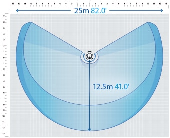
- High-accuracy measurement over a large area
- A wide measurement range up to 15 m (49.2′) can be measured with high accuracy. The WM Series is equipped with a navigation measurement mode, which enables measurement at the same point according to a memorized measurement procedure, allowing anyone to obtain the same measurement data.
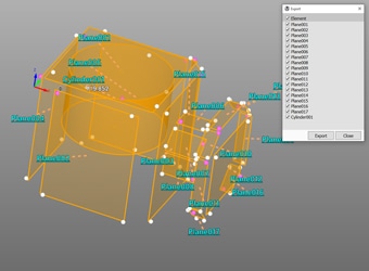
- Measurement results can be output as 3D models
- The measured elements can be exported as a STEP/IGES file. 3D CAD data can be created on the basis of the measurement results of an actual product even if no drawing is available.
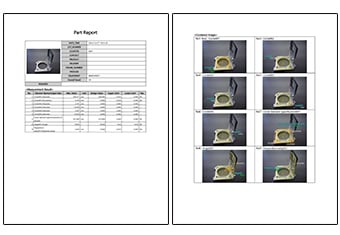
- Inspection reports can be created with photos
- Inspection reports can be automatically created with photos that allow you to understand measurement points at a glance. These inspection reports can not only gain you the trust of your business partners but also allow you to save measurement results as digital data, leading to higher efficiency of in-house data management.
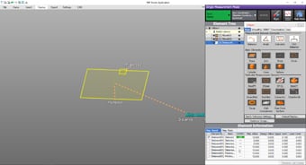
- Easy-to-understand interface
- CMM interfaces are often a mess of complex and unfamiliar commands. The WM Series provides intuitive operation using images and icons, so anyone can easily understand how to operate the system.
The WM Series strongly supports analysis, such as comparison with 3D CAD data, as well as measurement of the dimensions and shapes of the parts of pressure vessels. It dramatically improves the efficiency of manufacturing of pressure vessels and of work indispensable for their installation and quality management.
