
Dimensional Measurement of Turbine Blades

The operating accuracy of turbines directly affects energy conversion efficiency. There are various types of turbines, which are classified according to their power source, such as water turbines, steam turbines, gas turbines, and wind turbines. Among them, gas turbines are used for generators and aircraft jet engines and need to maximize their energy conversion efficiency.
This section explains dimensional and shape measurements of turbine blades, which are important parts of gas turbines, the necessity of these measurements, important measurement points, and methods for optimizing their measurement efficiency.
- What Is a Turbine Blade?
- Necessity of Dimensional Measurement of Turbine Blades
- Dimensional Measurement of Turbine Blades
- Problems of Dimensional Measurement of Turbine Blades and Their Solutions
- Optimization of Dimensional Measurement of Turbine Blades

What Is a Turbine Blade?

Gas turbine blades function as a rotating blade cascade while receiving the flow of a high temperature and pressure fluid generated by burning a fuel.
Generators obtain power for rotation by applying a high temperature and pressure fluid to the turbine blades in the shaft direction while rectifying the fluid flow with the stator, a stationary blade cascade. Gas turbines have high energy conversion efficiency. The gas turbine combined cycle (GTCC), which uses gas turbines, is most commonly used for new thermal power generating facilities because this technology emits approximately 50% less CO2, NOx, and other greenhouse gases and exhibits high power generation efficiency without using oil fuel.
Aircraft jet engines use a jet of energy discharged from nozzles as thrust without rotating the rotor. Engines that operate on this principle are called turbojets. Engines that have their energy conversion efficiency further enhanced using turbojets are called turbofans.
Necessity of Dimensional Measurement of Turbine Blades
The durability of turbine blades, which rotate at high speed under high temperature and pressure, greatly depends on the accuracy of their shapes and dimensions as well as materials. The accuracy of blade dimensions, in particular, affects the accuracy of rotor rotation. Errors in blade dimensions can cause eccentric rotation that could seriously damage bearings and other parts.
There are two types of turbine blades: forged blades manufactured by forging and cutting and cut blades manufactured by being cut out of square metal rods. Blades for large-scale turbines with diameters exceeding 3 m (9.8′) are manufactured with a combination of forging and cutting. During manufacturing, volumetric shrinkage due to cooling and shape defects due to inappropriate metal flow may occur in the forging process, and defects such as tearing and burrs may occur on cut surfaces in the cutting process.
Additionally, if the assembly accuracy of turbine blades replaced during maintenance is low, serious accidents may occur. For these reasons, dimensions and shapes need to be measured during processing and maintenance with careful attention to the following points.
During processing
Lacing wires, which are attached to reduce vibration of turbine blades, incline if the diameter and height of the holes through which they pass are out of their tolerances. Tilted lacing wires increase the stress applied to the turbine blade roots, which can cause the blades to crack. Additionally, if the dimensions of turbine blade roots are not accurate, turbine blades may burst or scatter due to centrifugal force generated during operation. The dimensions and shape have an especially direct affect on the strength when the roots use the fir-tree structure.
During maintenance
If the installation state or the toe shape of lacing wires becomes abnormal or the roots are deformed and their plane-to-plane contact state changes during turbine blade replacement, the blades may crack. Additionally, if turbine blades are reused, their installation accuracy may be reduced due to corrosion. The reduced installation accuracy may cause the shaft center to deviate and damage the bearings. Inspection using dimensional measurement is particularly important for the roots because this area is likely to undergo plastic deformation due to the heat and exhaust pressure generated during operation and stress generated by centrifugal force.
Inspection and test methods for turbine blades are strictly specified by various standards, such as the Japanese Industrial Standards (JIS), the International Organization for Standardization (ISO), the American National Standards Institute (ANSI), and the American Society of Mechanical Engineers (ASME), and the dimensions of turbine blade parts are also specified as essential measurement items. Aircraft jet engines are managed by the international system in which aircraft jet engines cannot be commercialized without being certified by the International Civil Aviation Organization (ICAO), which is a UN agency. Existing aircraft cannot fly without this certification, and aircraft gas turbines are also subject to this system. Unlike aircraft gas turbines, gas turbines for power generation have no broad international standard system, but there are some standards that specify how to test and evaluate their performance.
Dimensional Measurement of Turbine Blades
Strict tolerances are applied to the turbine blade shape and turbine shaft alignment to ensure the optimal blade positions and aerodynamic motion. Typical turbine blades are formed with free curves, which requires advanced measurement techniques.
Dimensional measurement points
Turbine blades have 3D shapes, so there are many very important measurement points. Among them, this section explains the following four most important points: diameter of turbine stages and blade shape, assembly accuracy, blade thickness, and shaft alignment.
Turbine stage diameter and blade shape
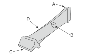
- A
- Shroud
- B
- Stub
- C
- Root
- D
- Blade surface
The turbine stage diameter, blade shape, lacing wire hole diameter and height are measured. A blade is comprised of a shroud, stub, and root. The dimensions and positions of all these parts must be confirmed to fall within their respective tolerances. The shroud, in particular, needs to be strictly measured because it is located at the tip of the blade and affects vibration of the rotating turbine. Additionally, turbine blades are twisted from the shroud to the root and blade cross-sections are formed with 3D curves. Many points need to be measured to understand the entire surface shape, which takes a lot of time. High-accuracy but efficient measurement is required.
Assembly accuracy
For thermal power generators, the number of blades in turbines can exceed 1000. To allow them to rotate accurately, it is important to measure not only the dimensional accuracy of each blade but also the assembly accuracy of blade intervals, root conditions, lacing wire installation conditions, toe shape, and other related elements. Strict dimensional measurement is required especially for the clearance between turbine blades and the blade ring that stores turbine blades, because the tolerance is as small as a few millimeters even for a turbine stage with diameters of a few meters. Typical clearance measurement uses feeler gauges. A feeler gauge in a size corresponding to each gap needs to be inserted into the gap at each measurement point to confirm that its width is within its dimensional tolerance.
Blade thickness
As turbine blades reach extremely high temperatures during operation, some blades are hollow to circulate a coolant internally. Turbine blades with this structure are called hollow turbine blades. Errors in the thickness of hollow turbine blades can hinder coolant circulation, reducing the cooling effect. This may cause unexpected accidents such as overheating. Therefore, blade thickness measurement is important to ensure an appropriate balance between optimal strength and cooling performance. However, accurate thickness values cannot be obtained without measuring the entire blade, which requires accurate 3D measurement. Analysis, such as checking with 3D CAD design data, is vital work.
Shaft alignment
The turbine shaft is aligned during rotating equipment maintenance. During alignment, shaft fixing jigs may bend due to gravity or jig backlash may affect measurement results. If coupling surfaces are rough or the shaft moves in the thrust direction, the measurement needs to take into account the errors caused by these factors. Measurers need to correct the influence from these factors to obtain an accurate shaft alignment value, which requires accurate measurement by experienced operators.
Problems of Dimensional Measurement of Turbine Blades and Their Solutions
It is important to measure not only finished turbine blades but also the assembly state and related elements of turbine blades during manufacturing. As turbine blades operate under high temperature and pressure, they are subject to various defects such as warpage, curvature, and cracks. Turbine stages that have been used for long periods need to undergo scheduled overhauls. It is difficult to transport large-scale turbine stages to a measuring room, so in-machine measurement functions on machine tools is needed. When turbine stages undergo periodic inspection or replacement, measuring instruments such as tape measures and calipers are used for their measurement. However, cumbersome work, such as repeated measurements at the same point, has to be performed to obtain high accuracy. This work needs to be optimized because of its impact on the operating rate.
Measurement of turbine stage diameter and small parts
Large-scale turbine stages with diameters exceeding 3 m (9.8′) are usually measured by at least two people. The large number of measurement points makes these measurements require a lot of time.Additionally, their complex shapes make some points unmeasurable. Values calculated from values at measurable points are used as the measured values in such cases.
The following are some examples of problems that may occur.
- The dimensions cannot be measured with tape measures because blades are in the way.
- Targets need to be placed on a machine tool such as a lathe.
- Measured values obtained with feeler gauges are not recorded and can vary among measurers.
With KEYENCE’s WM Series, it is possible for a single person to measure these workpieces. The intuitive operation of just touching the wireless probe to the measurement point allows the recessed areas of the target to be measured easily. It is possible to measure the dimensions of the blade parts, such as the shroud, stub, and root, as well as the diameter of turbine stages. 3D measurements, such as hole pitch, position, coaxiality, and flatness, can also be performed. Unlike measurements using measuring instruments such as calipers and tape measures, results do not vary among operators, enabling quantitative measurement.


Measurement of blade assembly accuracy
It is necessary to measure the parts of a turbine, including blades, without disassembling them during turbine maintenance. Assembled turbines are large and often have complex shapes, so it is difficult to measure their dimensions using tape measures and calipers. This makes measuring instruments that are capable of measuring 3D dimensions ideal.
Dimensional measurement of assembled turbines requires measuring instruments that can perform immediate on-site measurement with sufficient versatility for complex 3D shapes.
Use of laser trackers

- A
- Projector and receiver
- B
- Reflector
- C
- Tripod
For the reasons above, laser trackers may be used to measure the dimensions of assembled turbines.
A laser tracker is an optical measuring instrument that determines the 3D position of a measurement target by emitting a laser beam to a reflector in contact with the target so that the beam reflects back to the projector. Compared with typical bridge coordinate measuring machines (CMMs), laser trackers can measure larger targets (a few meters to tens of meters).
Laser trackers are useful for measuring huge targets such as turbines, aircraft, large-scale facility parts, and cut products machined in large-scale processing facilities.
Use of wide area CMMs
KEYENCE’s Wide Area Coordinate Measuring Machine WM Series is also a measuring instrument suitable for 3D measurement of large-scale products such as assembled turbines. The portability of the WM Series allows it to perform measurements anywhere. The WM Series can also be used in environments at operating temperatures ranging from 10°C (50°F) to 35°C (95°F) with relative humidity from 20% to 80%. There is no need for a temperature-controlled quality lab. These advantages enable high-accuracy, on-site 3D measurement without having to bring turbine blades into a measuring room. Parts can be measured on-site for periodic inspection. This reduces the downtime of turbines, contributing to higher operating rates.


Measurement of free-form curved surfaces
The WM Series enables perform 3D shape measurement of blades formed with complex curved surfaces. Even warpage and curvature, which are difficult to measure with tape measures and calipers, can be compared with CAD data and displayed with an easy-to-understand color map.


Measurement of GD&T and position coordinates
GD&T and coordinates cannot be measured accurately without using a CMM.
In addition to circularity, distance, and other basic measurements, the WM Series can perform virtual point measurements such as midpoint, GD&T measurements (flatness, etc.), and XYZ coordinate measurements. Even position coordinate measurement of workpiece fixing jigs, which usually requires experience, can be performed easily.


Optimization of Dimensional Measurement of Turbine Blades
The WM Series enables accurate 3D measurement of the shape of turbine blades with the simple operation of touching targets with the wireless probe. The WM Series also has the many advantages listed below.
- High-accuracy measurement over an area up to 15 m (49.2′)
- A wide range of up to 15 m (49.2′) can be measured with high accuracy using the wireless probe. Large-scale targets with measurement points that cannot be reached with bridge or arm CMMs or with hand tools like calipers can be measured easily.


- Single-person measurement of large products
- The easy operation of just touching the wireless probe to points to measure enables single-person measurement of large products. This can greatly reduce inspection costs.

- The portable body can be placed on-site
- The main unit can be carried around on the cart. Rather than having to move measurement targets, the WM Series can be brought to them.

- Check with 3D CAD data
- Comparison measurements are possible between a part being measured and a shape imported from a 3D CAD file. The points of difference between the part and the 3D CAD data can be displayed as a color map. This allows for measurement of free-form curved surfaces and profile tolerances.
The WM Series provides powerful support for not just shape measurements of turbine blade parts and position measurement of blades during assembly, but also for data analysis and inspection report creation. It dramatically improves the efficiency of manufacturing of turbine blades and of the indispensable for their maintenance and inspection.
