
Dimensional Measurement of Vacuum Chambers
With the spread of the fifth-generation technology standard (5G) and digitized automobile equipment, demand for semiconductors is said to have entered a supercycle*. Semiconductor manufacturing device manufacturers need to urgently develop new technologies and improve productivity in response to growing demand and higher functionality. The performance of vacuum chambers used in many semiconductor manufacturing processes are a particularly essential element for semiconductor manufacturing technologies that are always evolving.
This section introduces basic knowledge such as vacuum chambers applications in the semiconductor manufacturing processes, their structure, problems of shape and dimensional measurements that determine their performance, and solutions for these problems.
* A price increase that occurs at a constant frequency, a type of periodic market price fluctuation and economic cycle.
- What Is a Vacuum Chamber?
- Applications of Vacuum Chambers in Semiconductor Manufacturing Processes
- Vacuum Chamber Structure
- Necessity of Dimensional Measurement of Vacuum Chambers
- Dimensional Measurement of Vacuum Chambers
- Problems of Dimensional Measurement of Vacuum Chambers and Their Solutions
- Optimization of Dimensional Measurement of Vacuum Chambers

What Is a Vacuum Chamber?
A vacuum chamber is a container that creates a vacuum. Vacuum is a state in which pressure is lower than atmospheric pressure. Vacuum pumps are attached to a vacuum chamber to suction air from the vacuum chamber to create a vacuum in it.
The plasma required by many semiconductor manufacturing devices is generated in vacuum. A vacuum contains fewer impurities and lowers boiling points, making it possible to deposit thin films of desired materials or boil them. Thanks to these characteristics, vacuum chambers are used in many semiconductor manufacturing processes such as exposure, deposition, etching, and sputtering.
Applications of Vacuum Chambers in Semiconductor Manufacturing Processes
Vacuum chambers are used for many devices used in semiconductor manufacturing processes. Some typical devices are introduced in this section.
Chemical vapor deposition (CVD) device
A CVD device is used to produce thin films. A CVD device can deposit films that are approximately 10 to 1000 nm thick on silicon wafers, including films that protect semiconductors from water and dust, wiring films, and insulating films. Thin films are produced by chemical reactions of gases caused by heat, light, or plasma.
CVD devices that use plasma produce thin films in vacuum chambers. The method that uses plasma can produce thin films at lower temperatures than using heat or light. It can also produce thin films on narrow grooves, which allows it to be used in many semiconductor manufacturing processes.
Etching device
An etching device finely processes semiconductor surfaces, such as deep groove engraving with widths of approximately 100 to 1000 nm. Two types of etching devices are available: wet etching devices and dry etching devices. A wet etching device removes a thin film using a chemical reaction in a solution of acid, alkali, or other substances and further removes exposed areas. A dry etching device uses plasma in high vacuum. This method generates a plasma using gases in a vacuum chamber and removes a thin film through a chemical reaction and bombardment with accelerated ions.
Compared with wet etching devices, dry etching devices which use plasma can perform finer processing and provide better aeolotropy. Additionally, some recently developed dry etching devices use high-density plasma that can maintain throughput even for large-diameter wafers.
Sputtering device
A sputtering device produces thin films in vacuum.
This device generates an argon plasma in a vacuum chamber. In the chamber, the sputtering device makes argon ions collide with an ingot, called a target, to eject metal atoms and deposit them on wafers.
Sputtering devices can deposit thin films of metals that are difficult to deposit with CVD devices and vacuum deposition methods, such as metals with high melting points and alloys. At the same time, the vacuum level in a vacuum chamber needs to be approximately two digits higher than that of CVD devices, which requires a highly effective vacuum system.
Extreme ultraviolet lithography* (EUV) exposure device
EUV exposure devices are the latest exposure devices that use a soft X-ray as a light source. The soft X-ray used in this technology has a wavelength of 13.5 nm, approximately one-tenth or less than a conventional ArF light source. Using light with an extremely short wavelength can transfer circuit patterns as fine as 5 nm and 3 nm onto wafers, which was difficult with conventional technologies.
The soft X-ray used in EUV exposure devices is emitted in a vacuum chamber and the optical system including an irradiation mirror is also located in the chamber. Soft X-rays are absorbed in air. This requires a high vacuum level and water removal in the chamber.
Although EUV exposure devices are not yet in widespread use, they are expected to become the leading edge of exposure equipment and semiconductor manufacturers are competing fiercely to install them. EUV exposure devices, initially introduced in the manufacturing processes of logic semiconductors, are also seeing use for dynamic random-access memories (DRAMs), which are experiencing significant die shrinks and becoming much faster with much larger capacities. EUV exposure devices are expected to further spread in this field.
*Extreme ultraviolet
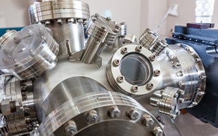
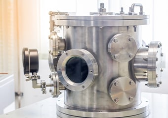
Vacuum Chamber Structure
Vacuum chambers achieve vacuum by lowering the pressure using a roughing vacuum pump and a vacuum pump (main pump). Typical vacuum chambers are manufactured from stainless steels or mild steels plated with nickel, while ultra-high vacuum systems are manufactured from aluminum alloys.
Wafers are fed into a vacuum chamber and undergo processing, such as deposition and etching, in the chamber. To perform high quality processing with minimum impurities and high adhesion, the vacuum chamber needs to achieve high vacuum to minimize impurities in air as much as possible. Some of their parts, such as flanges used to install components of vacuum chambers, need to be machined with high accuracy.
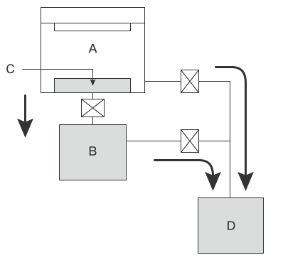
- A
- Vacuum chamber
- B
- Vacuum pump (main pump)
- C
- Wafer
- D
- Roughing vacuum pump
Necessity of Dimensional Measurement of Vacuum Chambers
The performance of semiconductor devices is directly related to the level of vacuum in a vacuum chamber. Abnormal vacuum levels have negative influences on physical and chemical processing, such as electric discharge, ionization, and sputtering, especially in devices that generate plasma.
One of the major causes of negative influences is a phenomenon called an air leak. In this phenomenon, air enters a vacuum chamber through gaps on end faces or sealing surfaces of the chamber. If air leaks into a vacuum chamber, its vacuum level lowers, which interferes with the chemical reactions required for deposition, etching, sputtering, and other processes, causing processing failures.
Gases may also leak due to joint failures of connectors or welded sections, or installation failures of packing materials or other parts, causing inhalation gas poisoning, fire, or explosions.
Air and gas leaks can be prevented by taking careful measures such as ensuring the flatness of end faces and sealing surfaces of vacuum chambers, testing the airtightness of gas flow systems including flange installation states, and purging these gas flow systems with inert gases. However, the most important thing is to strictly measure their shapes and dimensions during manufacturing.
Dimensional Measurement of Vacuum Chambers
Vacuum chambers are manufactured from stainless steels, nickel-plated mild steels, and aluminum alloys by joining sheet metal (generally by welding), machining blocks, or forging. It is necessary to inspect for strain caused by welding when a vacuum chamber is joined by welding and deformation caused by cutting pressure or other factors when a vacuum chamber is manufactured by machining or a combination of forging and machining.
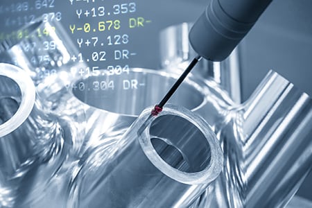
Dimensional measurement points
There are many points that need to be measured. This section introduces the flatness of end faces and sealing surfaces of a vacuum chamber, for which shape and dimensional accuracy is most strictly required, the assembly accuracy of gate valves (vacuum valves), and precautions for these measurements.
Flatness of end faces and sealing surfaces
The flatness of end faces and sealing surfaces of openings and joints with covers of a vacuum chamber must be measured.
The side length of large-scale rectangular vacuum chambers or the diameter of large-scale cylindrical vacuum chambers can exceed 1 m (3.3′). Even subtle errors may prevent appropriate joining, causing problems such as leaks. Errors in the flatness will also affect the operational accuracy of vacuum chambers after installation.
Careful inspection is required, including machining accuracy measurement in each manufacturing process and checking against CAD design data.
Assembly accuracy of gate valves (vacuum valves)
A gate valve separates a vacuum from another vacuum or a vacuum from ambient air. In semiconductor processing devices, gate valves are installed between the vacuum chamber and vacuum pumps to regulate the pressure in the vacuum chamber.
Gate valves separate a vacuum from ambient air while retaining the vacuum, so their assembly accuracy directly affects the airtightness of vacuum chambers. Low assembly accuracy can cause gaskets to malfunction, causing air or gas leaks in vacuum chambers during operation.
The assembly accuracy of gate valves, such as angles and positions, needs to be strictly measured.


Problems of Dimensional Measurement of Vacuum Chambers and Their Solutions
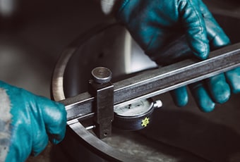
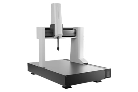
It is important to measure the shape and dimensions of each part before assembly and of assembled vacuum chambers. It is common for these measurements to require three-dimensional control items and accuracy on the order of micrometers, so there is a limit to how well hand tools, such as tape measures and calipers, can perform in these situations. Hence, bridge CMMs are widely used for these measurements.
However, it takes a lot of work to move large-scale vacuum chambers from the manufacturing site to a measuring room and set them on a CMM. This method also poses the problem of being unable to measure promptly when on-site measurement is necessary. Another problem is that high-level measurement skills and two or three people are required to measure large-scale chambers such as those larger than 1 m (3.3′).
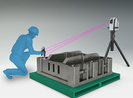
To solve these problems, the latest CMMs are used in an increasing number of cases. KEYENCE’s Wide Area Coordinate Measuring Machine WM Series enables a single person to perform high-accuracy dimensional measurement of large-scale vacuum chambers with the wireless probe. Even recessed areas of workpieces can be reached with no movement restrictions within the measurement range, which allows for measurement with the simple operation of touching targets with the probe. Additionally, the WM Series is portable, allowing for measurements of any points when you want whether at manufacturing sites or installation sites. Unlike measurements using hand tools, measured values do not vary, enabling quantitative measurement.

Flatness measurement of end faces and sealing surfaces
Large-scale vacuum chambers are approximately 5 m (16.4′) long and 3 m (9.8′) wide with weights of approximately 4 tons. Even for large-scale vacuum chambers, a high level of measurement accuracy is required in many cases. To measure the flatness and dimensions of each part with accuracy, a bridge CMM is required. However, measuring a large-scale vacuum chamber with a bridge CMM requires the difficult work of removing the chamber from the machine tool and moving it to a measuring room.
Measurements performed on machine tools using hand tools also present many issues. For example, it is not possible to measure 3D dimensions with these tools and measurements take time, decreasing the operating rate of machine tools. Additionally, when vacuum chambers are fine-adjusted while the final accuracy is checked, it is preferable to measure their dimensions on machine tools instead of removing them. Therefore, for dimensional measurement of large-scale vacuum chambers, a CMM that is compact, portable, and capable of measuring the large area of a vacuum changer set on a machine tool is ideal.
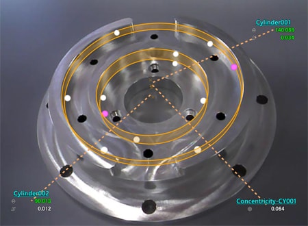
The WM Series can even measure large-scale vacuum chambers set on machine tools without having to remove them. It enables easy single-person measurement of various elements of machined chambers, such as diagonal dimensions, flatness, and circularity, leading to more efficient fine adjustments of machining accuracy during manufacturing as well as ensuring the final dimensions.


Assembly accuracy measurement of gate valves
The accuracy of the assembly angle and position of gate valves assembled on a large-scale vacuum chamber is measured on the basis of the vacuum chamber. The measurement distance is several meters, so their positions are measured using tape measures or calipers and their angles are measured using levels or similar measuring instruments. However, measured values obtained with these hand tools vary according to the angle and strength at which the tools are applied to the target, which makes it impossible to prevent variations in measured values among operators.
With the WM Series, it is possible for a single person to perform quantitative measurement by simply touching measurement points with the probe. Simply by touching the target with the probe, the operator can measure not just the distortion and strain caused by welding but the installation angle of the gate valves as well. Even 3D position coordinates can be measured. Deviations from designed tolerances can also be judged instantaneously.


Optimization of Dimensional Measurement of Vacuum Chambers
The WM Series enables single-person measurement of the shapes and dimensions of the parts of large-scale vacuum chambers with the simple operation of touching with the wireless probe. In addition to the features introduced above, the WM Series has the following advantages.
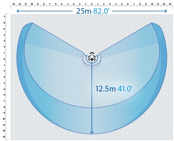
- High-accuracy measurement over a large area
- A wide measurement range up to 15 m (49.2′) can be measured with high accuracy. The WM Series is equipped with a navigation measurement mode, which enables measurement at the same point according to a memorized measurement procedure, allowing anyone to obtain the same measurement data.
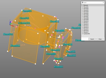
- Measurement results can be output as 3D models
- The measured elements can be exported as a STEP/IGES file. 3D CAD data can be created on the basis of the measurement results of an actual product even if no drawing is available.
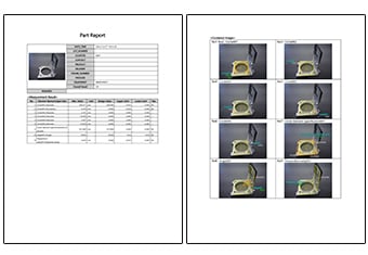
- Inspection reports can be created with photos
- Inspection reports can be automatically created with photos that allow you to understand measurement points at a glance. These inspection reports can not only gain you the trust of your business partners but also allow you to save measurement results as digital data, leading to higher efficiency of in-house data management.
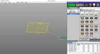
- Easy-to-understand interface
- CMM interfaces are often a mess of complex and unfamiliar commands. The WM Series provides intuitive operation using images and icons, so anyone can easily understand how to operate the system.
The WM Series strongly supports analysis, such as comparison with 3D CAD data, as well as measurement of the dimensions and shapes of the parts of vacuum chambers. It dramatically improves the efficiency of manufacturing of vacuum chambers and of work indispensable for their installation and quality management.
