For Individuals Looking for Thickness Measurement Systems
When looking for the best way to measure thickness, there are a number of important factors to consider, including the shape and material of the target and the type of measurement system. Selecting equipment that doesn't adequately meet your needs can lead to insufficient precision and increased man-hours during production, so make sure you choose the right equipment. This site is designed to help those looking for a thickness measurement system discover the best way to perform measurement with confidence.
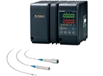
When light is directed at a transparent target, light is reflected from the top and bottom surfaces. Thickness is measured by calculating the difference in position of the light reflected from the top and bottom surfaces.
A
Front (Peak 1)
B
Back (Peak 2)
C
Transparent glass
KEY POINTS
Displacement sensor selection is important
Does the displacement sensor have enough range to see both the top and bottom surfaces?
Check to see if stable measurement is possible even if the reflectance of the top and bottom surfaces is different.
Spectral Interference Method Ultra-high resolution of 1 nm 2 mm microprocess sensor head
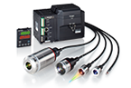
Sensor heads are installed so that the top surfaces of the roller and target are projected as a single plane on the captured image. Thickness is found by measuring step from the roller to the top of the target.
KEY POINTS
The thickness of both transparent and opaque targets can be measured. Since the thickness of targets is measured in reference to the roller, ensure that no clearance is formed between the roller and the target.
2D Telecentric Optical Method. Simultaneous measurement of up to 100 with calibrated high-speed measurement.
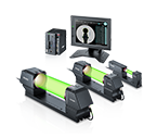
Thickness is measured by the difference in height when the target is wound around (i.e., held in close contact against) the roller with the roller surface taken as the zero point.
KEY POINTS
The thickness of both transparent and opaque targets can be measured. Since the thickness of targets is measured in reference to the roller, ensure that no clearance is formed between the roller and the target.
When light is directed at a transparent target, light is reflected from the top and bottom surfaces. Thickness is measured by calculating the difference in position of the light reflected from the top and bottom surfaces.
A
Front (Peak 1)
B
Back (Peak 2)
C
Transparent glass
KEY POINTS
Displacement sensor selection is important
Does the displacement sensor have enough range to see both the top and bottom surfaces?
Check to see if stable measurement is possible even if the reflectance of the top and bottom surfaces is different.
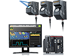
Thickness is found by simultaneously measuring the base surface and target using a 2D laser displacement sensor and measuring step from the obtained profile.
A
Obtained shape
KEY POINTS
Errors occur when there is a gap between the target and the reference surface.
Use a base surface with high precision, such as a surface plate.
Use vacuum contact or magnetic contact.
Improving mounting using the above steps will significantly improve measurement accuracy.
Precautions during Measurement of Thickness between Two Sensor Heads
About optical-axis alignment
When you measure a workpiece between two sensor heads, the measured thickness will not change, in principle, even if the workpiece vibrates up and down. However, if the optical axes of the two sensor heads are not aligned with each other into a straight line, measurement errors may be caused due to the workpiece vibrating up and down or bending. Pay attention to the following points and arrange the installation so that the optical axes can be aligned.
To minimize the effect of the optical axes being misaligned, install sensor heads close to the rollers and select a location where the workpiece tension is stable and the distance from one roller to the next is small. This makes it possible to perform measurements with small amounts of workpiece bending and vibration.
Orient the sensor heads so that the directions of the projected and received light are perpendicular to the direction of movement of the workpiece, as shown in the figure. This makes it difficult for the sensor heads to be affected by tilting and shaking in the workpiece's direction of movement due to vibration during transportation.
During optical-axis alignment, measure a thin white plate of resin or a piece of paper as the temporary measurement target. When you measure these targets, the laser spots pass through the target and can be seen. Install the sensor heads so that the spots on the front and back of the target are always aligned even if the target is moved up and down.
[Reference] Check that the spots on the front and back of the target are always aligned even if the target is moved up and down.
The laser spots are slightly misaligned.
The laser spots are aligned.
Set the sensor heads so that the centers of the laser spots are aligned even if the target is moved up and down.
Precautions during Thickness Measurement above a Roller
About the gap between the roller and the workpiece
When measuring the thickness of a workpiece on a roller with this roller as the reference, measurement errors will occur if there is a gap between the roller and the workpiece. Pay attention to the following points and arrange the installation so that no gaps occur.
Apply as much tension to the workpiece as possible. If the tension is weak, the workpiece will not be in full contact with the roll, so a gap ranging from a few micrometers to some tens of micrometers will occur. We recommend that you perform measurements with a tension of 50 N or more applied, but be sure to consider the tensile strength of the workpiece. Perform measurements from a location in which the workpiece tension is as stable as possible, the distance from one roller to the next is small, and the workpiece is positioned on top of the roller.
Align the optical axis with the peak position of the roller. As shown in the figure, if the optical axis is misaligned from the peak position of the roller, a measurement error (gap Z) occurs.
Install a mechanism that makes it possible to fine-tune the sensor head position in the feed direction.
Perform measurements on a roll with a large diameter to minimize gap Z even if the optical axis is misaligned from the peak position of the roll.
You will have to make modifications such as those listed here.
About roller eccentricity
When a roller rotates, measurement errors may be created due to the eccentricity of the roller. Pay attention to the following points to cancel the influence of roller eccentricity.
When the locations used to measure the thickness are both edges of the workpiece, measure both the roller surface and the workpiece surface at the same time to find the thickness from the step value.
When measuring a workpiece on a roller with the roller as the reference, you can perform measurements at the same rotation angle (position) to cancel the influence of eccentricity even if the roller moves in an eccentric manner.