
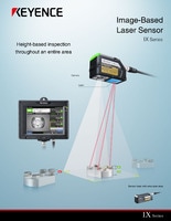
Image-Based Laser Sensor
IX series
Sensor amplifier main unit IX-H2000
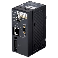
*Please note that accessories depicted in the image are for illustrative purposes only and may not be included with the product.
Specifications
Model | IX-H2000 | |||
Main unit / expansion unit | Main unit | |||
Display | Min. display unit | Z axis | 10 μm *1 | |
X axis | 50 μm *1 | |||
Display range | Z axis | ±999.99 to ±999 mm 39.33" (with 4 selectable steps) *1 | ||
X axis | ±999.95 to ±999 mm 39.33" (with 4 selectable steps) *1 | |||
Tools | Scan mode | Height, Step, Average height, Pin height, MAX/MIN, Height area, Monochrome area, Width, Step calculation, Thickness calculation, | ||
Line mode | Height (Ave./Max./Min.), Step (Ave./Max./Min.), Edge position, Width/diameter, Step/width calculation, Thickness calculation, | |||
Other functions | Common | Zero/offset, Operating threshold adjustment, 2-point calibration, Measurement direction, Position correction NG measurement, Zero/offset recording, Capture mode (HDR), | ||
Scan mode | Measurement range, Measurement position (small/standard/large), Measurement mode, Measurement noise elimination, Imaging mode (high gain), | |||
Line mode | Average count, Laser position adjustment, Timing input, Head tilt correction (fixed only), Ambient light removal for measurement, | |||
Input | Input | Switchable between non-voltage input and voltage input | ||
Number of inputs | 8 (IN1 to IN8) | |||
Function | IN1: External trigger ↑↓ / Timing input, IN2 to IN8: Enable by assigning optional functions | |||
Output | Output | Open collector output; NPN/PNP switchable, N.O./N.C. switchable | ||
Number of inputs | 10 (OUT1 to OUT10) | |||
Function | Enable by assigning the optional functions | |||
Analog voltage output | ±5 V, 1 to 5 V, 0 to 5 V, Output impedance: 100 Ω *4 | |||
Analog current output | 4 to 20 mA, Max. load resistance: 350 Ω *4 | |||
Number of programs | 32 | |||
Statistical information | Scan mode: Measured value / Degree of similarity (Max., Min., Ave.), Processing time (Latest, Max., Min., Ave.), Count (Number of OKs / Number of NGs / Number of triggers)
| |||
Detection history | Saved history | Scan mode | 50 (FTP client function: Enabled/High-resolution mode: Enabled) | |
Line mode | 400 (FTP client function: Enabled/High-resolution mode: -) | |||
Save conditions | Selectable between NG only and All *6 | |||
Image data transmission (FTP client function) | Destination | FTP server | ||
Method | Selectable between bmp, jpeg, and txt | |||
Conditions | 4 conditions | |||
Ethernet | Standard | 100BASE-TX/10BASE-T *7 | ||
Connector | RJ45 8-pin connector *7 | |||
Interface compatibility | CC-Link, DeviceNet®, EtherNet/IP®, EtherCAT®, RS-232C, BCD output, TCP/IP non-procedural communication *8 | |||
Number of connectible units | Main units: 1, Expansion units: 1, Communication units (DL): 1 | |||
Ratings | Power voltage | 24 VDC ±10% (including ripple) | ||
Current consumption | Max. 1.9 A or less (With main unit only: 0.8 A or less, With unit expansion: 1.9 A or less) (Excluding output load) *9 | |||
Environmental resistance | Ambient temperature | 0 to +50°C 32 to 122°F (No freezing) | ||
Relative humidity | 35 to 85% RH (No condensation) | |||
Material | Main unit case: PC / Power connector: PA, POM / Analog output connector: PA, POM / I/O connector: PA / | |||
Weight | Approx. 210 g | |||
*1 For displaying on an IX Series control panel or PC software. | ||||
![NR-X Data Logger / Data Acquisition Direct connection to other KEYENCE products [Click Here to Learn More!]](/Images/nr-x_series_300_300_01_2089589.jpg)