![Learn the Basics of Continuous Inkjet Printers [CIJ Central]](/Images/ss_products_inkjet_header_title_1785688.gif)
Internal structure of continuous inkjet printers
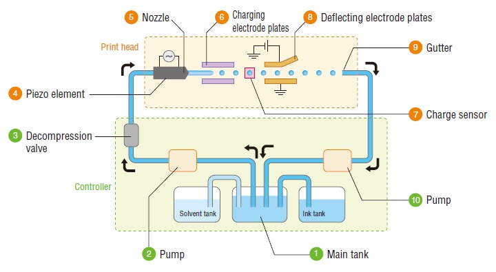
This section explains the internal path and ink circulation principle of industrial inkjet printers.
CIRCULATION PATH
Circulation principle
-
1Main tank
Stores the ink used in printing. Ink recovered from the gutter is also returned here.
-
2Pump
Pressurizes and feeds the ink from the main tank to the print head.
-
3Pressure reducing valve
Adjusts the ink pressure.
-
4Piezoelectric element
Oscillates the ink stream discharged from the nozzle to separate into ink particles.
-
5Nozzle
Discharges the ink.
-
6Electrostatic electrode plates
Applies a negative electric charge to the ink particles created from the ink stream.
-
7Electrostatic sensor
Monitors whether the ink particles have the proper electrostatic charge in them.
-
8Deflecting electrode plates
Generates a magnetic field between the electrode plates to deflect ink particles according to their charge. This directs ink particles onto the print target.
-
9Gutter
Collects the ink particles that are not used in printing.
-
10Pump
Retrieves the ink particles from the gutter and feeds them to the main tank.
-
1Main tank
Repeats the ink circulation.
- Solvent tank
- Supplies solvent to control viscosity when the ink in the main tank becomes too thick.
- Ink tank
- Supplies ink to the main tank when it is empty or when the ink is too thin.


![Inkjet Printer Tech Guide [Basic Knowledge Edition]](/img/asset/AS_114378_L.jpg)