Roll Coating
Overview of roll coaters
Roll coater systems are used for coating flat targets (substrates) through a combination of multiple different rollers to obtain the desired coated surface. Coating systems that use rollers are able to support various coating fluid viscosities and different coating thicknesses through the combination and specialization of many different technologies. As a result, roll coaters have been adopted in various industrial fields, including electronic components, optical and LCD products, food, and medicine.
In general, use is limited to the coating of relatively thin flat targets such as films and sheets. However, wide and long substrates (targets) can also be coated continuously and quickly. These systems are mainly used for wet coating. In some cases, the process is performed in a clean room to prevent the adhesion of foreign particles on the wet surface before solidification.

Types of roll coater methods
Roll coater methods can be classified based on the state of the coating fluid before coating and whether the coating amount is determined before or after coating. Although some systems employ several methods, this section describes examples of typical coating methods.
The classifications below are merely examples. There are various ways to classify the types, and some may differ from the descriptions below.
Open coating
This method usually has a coating head and a coating reservoir with pooled coating fluid that is exposed to the atmosphere. Typical examples are gravure coaters and reverse coaters.
Gravure coaters
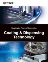
- Example of a direct gravure coater
-
- A. Backup roll
- B. Gravure roll
- C. Doctor blade
- D. Coating reservoir
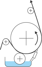
A gravure roll with an unevenly engraved surface is immersed in the coating fluid in the reservoir. After the coating fluid on the surface of the gravure roll is wiped off with the doctor blade, the fluid remaining in the pits are transferred onto the web of the target (substrate). Changing the coating thickness requires changing the gravure roll to one engraved with a different pattern. Offset gravure coaters provide a smooth and even coated surface at high speeds.
Reverse coaters
- Example of a reverse coater
-
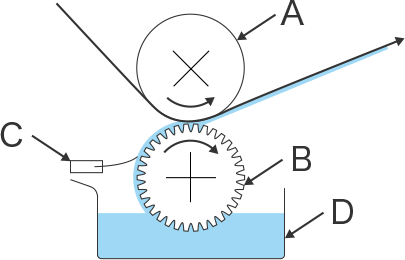
Typical reverse coater 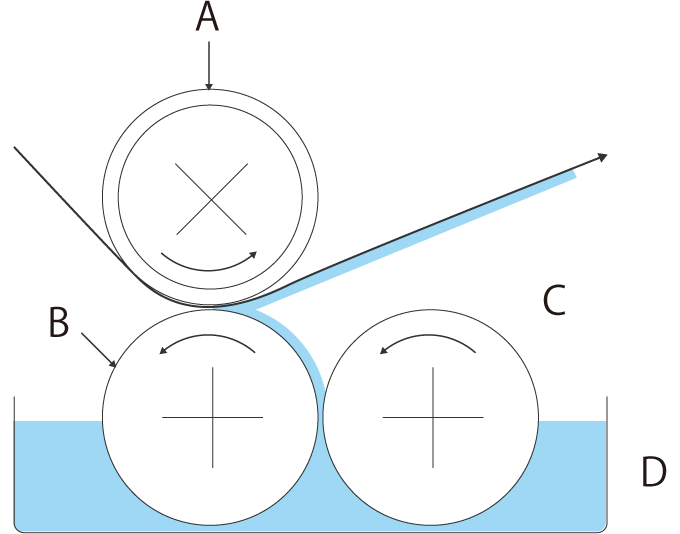
Reverse coater supporting high-viscosity fluids 
-
- A. Backup roll
- B. Applicator roll
- C. Metering roll
- D. Coating reservoir
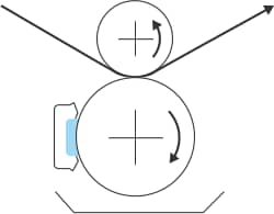
Reverse coaters usually consist of an applicator (coating) roll, a backup roll, and a metering roll. The backup and applicator rolls rotate in the same direction to transfer the coating fluid onto the substrate web. The coating thickness is determined by the gap between the applicator roll and metering roll as well as their speed. Care must be taken to prevent unstable rotation due to improper roll assembly, and the accuracy of the gap between the rolls must be noted.
Closed coating
This method prevents coating fluid from being exposed to the atmosphere before coating. This makes it easier to maintain coat quality depending on the coating fluid. Slot die coaters and lip coaters adopt this method.
Slot die coaters
- Example of a slot die coater
-
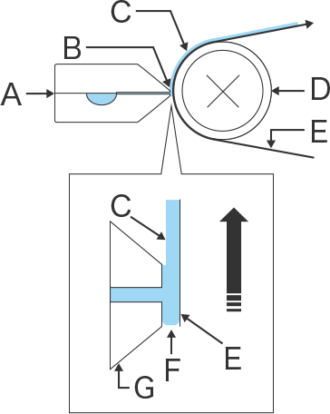
- A. Die
- B. Die lip
- C. Coating
- D. Backup roll
- E. Substrate (web)
- F. Coating fluid
- G. Die head
Die coaters adopt technology used in extrusion molding to execute the coating process. Coating fluid is passed through a die to create a uniform film, and the film is applied on the substrate to achieve coating. Because the coating fluid is pressure-supplied to the die from an enclosed tank, the fluid is not affected by air, resulting in stable coating.
A slot die coater is a typical die coater that uses a die designed to ensure a uniform amount of coating fluid in the width direction. A shearing force smooths the coat beween the the end of the die, the die lip, and the backup roll.
In recent years, coating efficiency has been improved with more sophisticated coaters such as multi-layer slot die coaters that coat multiple layers simultaneously.
Lip coaters
- Example of a lip coater
-
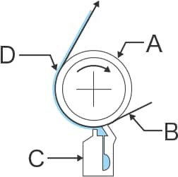
- A. Backup roll
- B. Substrate (web)
- C. Lip nozzle
- D. Coating
Lip coaters include a numerically-controlled coating head that allows easier quality control. Coating fluid is supplied to the lip nozzle from a lower cavity to the upper cavity at the end of the lip nozzle, where it is applied to a moving substrate. The end of the lip is rounded to generate a shearing force between the tip and the substrate during coating application.
Post-metering coating
"Pre-metering" coaters are coaters that determine the amount of coating at the time of application.
Conversely, coaters that apply additional coating and then remove excess to achieve the target amount are categorized as "Post-metering" coaters. Knife coaters and blade roll coaters fall into this category. The amount to be removed and the coating thicknesses are mechanically set based on the shape of the roll and the set gap.
Knife coaters
- Example of a knife coater
-
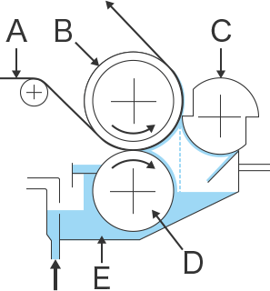
- A. Substrate (web)
- B. Backup roll
- C. Knife roll
- D. Applicator roll
- E. Pan
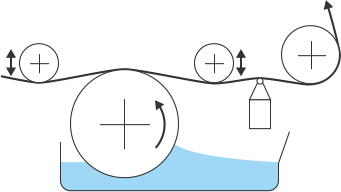
Knife coaters consist of a knife roll, backup roll, and liquid dam. The coating fluid in the liquid dam is transferred onto the substrate web through the gap between the turning backup roll and the fixed knife roll. The coating thickness is set based on the gap between the backup roll and the knife roll. With knife coaters, ensuring the accuracy of the backup roll assembly, knife roll blade, and adjustment of the gap between the rolls is important. It is also important to prevent jumping at substrate seams, which affects coating stability and can cause fluid leakage.
Blade roll coaters (with comma-type circular blades)
- Example of a blade roll coater
-
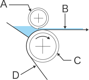
- A. Applicator roll
- B. Coating
- C. Backup roll
- D. Substrate (web)
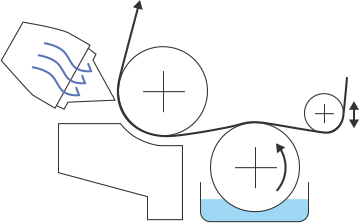
Blade roll coaters are characterized by an applicator roll with a blade, which is called a circular blade, or a comma blade, for its shape. Coating fluid is pooled between the applicator roll and the substrate, and the blade on the roll wipes off excessive fluid to ensure an optimum coating thickness. This method is generally suited for highly viscous coating fluids or when forming a thick coating. However, some models can support various coating thicknesses.
Examples of other methods
In addition to the above, various other methods are available according to the coating purpose or the properties of the substrate or coating fluid. Some use applicator rolls in different shapes, various reverse rolls and offsets, or a combination of other rollers and methods. The following introduces a few such examples.
Blade coaters
A doctor blade and backup roll maintain uniform thickness to allow smooth coating at high speeds. With this method, streaks (linear defects) are a concern.
Chamber doctor coaters
Coating fluid is supplied from a chamber, which prevents the emission of solvent smells and changes in viscosity while also allowing for easy blade replacement. This method can be used for direct gravure coating or reverse gravure coating.
Bar coaters
After coating, a bar makes the coated surface uniform. This system is suitable for small-quantity and high-speed coating of undercoats and topcoats.
Air knife (air doctor) coaters
These coaters are suitable for water-based coating fluids. After coating, pressurized air is applied to make the coated surface uniform. This method is less affected by the substrate thickness or uneven surfaces.
Present state of roll coaters
In addition to the above, many different coaters and combinations have been used to achieve smooth coating and pattern printing with high accuracy and at high speeds under various conditions. The section describes a variety of materials and end products that require coating technology.
Expanding coating applications
The demand for mass production using thin film coating technology has been growing as a result of thinner and more functional smartphones and tablets, the miniaturization and increased density of their components, the expanding demands for secondary batteries and solar cells, and the advanced performance of automobiles, construction materials, and fabrics.
- Functional films for optical products (organic ELs, TFT LCDs, touch panels, etc.)
- Light control (LR) films, anti-reflection (AR) films, anti-glare (AG) films, polarizing films, TAC films, light diffusion films, hard coat (screen protection) films, transparent conductive (ITO) films, index matching films, optical clear adhesive (OCA) films, flexible printed circuits (FPC), prism sheets
- Secondary batteries and solar cells
- Secondary battery electrode plates, secondary battery separators, reflector films, light-shielding films, photoresist films, decorative films, window films, heat dissipating films, solar cell back sheets, thin-profile battery laminates
- Electronic components and semiconductors
- Flexible printed circuits (FPC), photoresist films, polyimide (PI) films, laminated ceramic capacitors
- Other functional films and sheets (automobile, housing, fabric, medical, etc.)
- Leather sheets, carbon fiber products, airbags, heat insulation sheets, wallpaper, cushion flooring (CF), prepreg, non-woven fabrics, felt, mats, carpeting, waterproof moisture permeable sheets, adhesive tapes, transdermal absorption medicine sheets, barrier packaging films
Development and trends of systems
One of the problems of operating roll coaters is the sizable equipment necessary for large dimensions of the substrates, and the extensive changeover work required. In recent years, some devices have adopted cassette-type rollers to make changing coating conditions easier.
While the equipment has become more sophisticated and complicated, the need for measuring, monitoring, and recording the states of the coated surfaces, equipment, and substrates (targets) through the use of laser displacement sensor, cameras, and sensors has also increased.


