Servo Motors / Servo Systems

Product Lineup : AC Servo Motors


While general motors rotate 360°, servo motors turn within a certain range at the desired angle. They have robust structures that endure continuous operation and frequent starts and stops. Servo motors are used in a variety of factory automation equipment, including positioning devices and industrial robots.
Servo motors come in two types: AC and DC. As DC servo motors have durability and maintenance issues, AC servo motors have become the mainstream in recent years. AC servo motors do not have wear components like brushes, and can withstand long-term continuous use. Torque control is also possible over a wide rotational range, from low to high revolution ranges.
Another kind of motor with functionality similar to servo motors is stepper motors. Stepper motors have excellent responsiveness and synchronization, which makes them suitable for low-to-medium speed operations. For this reason, AC servo motors work well with systems that require a range of control, including rotational speed and torque, while stepper motors are more suited for equipment with repeated short strokes or equipment that needs good responsiveness.
Servo motors are characterized by their high torque and high accuracy in the high-speed range. The feedback control provided by the control devices called servo amplifiers (or servo drives) means that these motors are also used in positioning devices that require high precision, systems that need long strokes, and equipment with high-speed rotation. Let’s look at the structure of an AC servo motor, which provides these functions, and its working principle and application in the network environment.
Servo Motor Structure
An AC servo motor consists of a stator, made of an iron core and windings (stator coil), a rotor, which has a permanent magnet, a shaft, and an encoder (detector). They can be both compact and lightweight, and are installable on robot arms and in other small spaces.

A: Stator (iron core and windings) B: Rotor C: Shaft D: Encoder (detector)
Servo Motor Working Principle
An AC servo motor detects the position of the magnetic field using a device called an encoder in order to control the magnetic field. While encoders can be optical or magnetic, the basic principle of optical encoders is explained below.
The encoder’s fixed slit allows it to detect the position of the rotor using the light passing through the slit in the rotating disk, which helps identify the position of the windings, which is necessary for rotating the motor. Magnetic force is generated when current passes through the windings in the position perpendicular to the rotor’s magnetic pole, rotating the motor.
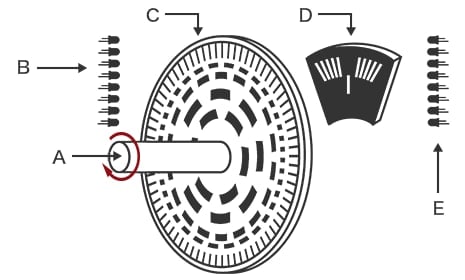
A: Shaft B: Light emitting diode C: Rotating disk D: Fixed slit E: Phototransistor
Servo Motor Control
An AC servo motor can control the rotational angle, speed of rotation, torque, and other factors as needed to perform various motions. The status of the AC servo motor is transmitted to the servo amplifier (servo drive). The servo amplifier compares the information it received from the AC servo motor with the correct operating status. Then it quickly communicates the correction value calculated from the comparison result in the form of power supply. The AC servo motor operates according to the power supply from the servo amplifier, which allows for sophisticated system control. This is commonly called the feedback control. In the case of AC servo motors, the transmission of information occurs only between the motor and the servo amplifier, so it is specifically called closed-loop control.
Benefits of Servo Motors / Servo Systems
AC servo motors provide high-speed motion with a large degree of freedom. This is made possible by closed-loop control, which can freely control the rotation angle, speed, and torque.
AC servo motors are equipped with an encoder. The encoder provides feedback about the motor axis rotational position and rotating speed to the amplifier unit. The amplifier unit compares the rotary torque, rotating speed, and position with the settings and uses the differences as feedback to the AC servo motor for detailed rotational adjustment. This mode of control is called closed-loop control, which provides smooth high-speed motion with stable torque and long-stroke positioning over a broad variable speed range from low to high RPM, as well as high torques in the high RPM range. By controlling the current during continuous operation and short-duration operation, even compact lightweight AC servo motors can provide high rotary torque for the load torque.
AC servo motors can provide smooth motion compared to stepper motors. Switching speed and torque is done seamlessly for human-like sensitive motions.
With an AC servo motor, the encoder detects the rotation angle and speed and controls the motor rotation with electric current, which allows for smooth motions. In contrast, stepper motors control the rotation angle and speed with the pulse frequency. The rotation angle per pulse is fixed, and a motor rotates through that angle every time it receives a pulse signal. This creates a stepped rotation with excitation switching, which is not smooth rotation. AC servo motors do not suffer from the limitation of steps due to their analog current control. This allows for the smooth motions of industrial robots and human-like motions of varying strength as needed.
AC servo motors do not have the brush-and-commutator contact, which eliminates wear-check maintenance and part replacement for the motors, and ensures longer life. AC servo motors are also free from electrical and physical noise.
With brushed motors, the brush contacts the commutator during use, causing significant friction. For this reason, brushed motors need to be periodically checked for wear that leads to replacement, which incurs costs. Brushed motors also tend to cause electrical and physical noise. AC servo motors do not have a brush or commutator. This means the maintenance burden and running costs are lower because there are no consumables. AC servo motors also have no friction-induced noise during use. Since AC servo motors do not generate electrical noise, they present no risk of other equipment being affected. Also, as there is no danger of sparks from the brush, AC servo motors can be used safely even in dangerous conditions, such as in explosive gas atmospheres or where a significant amount of dust is present.
Servo Motors / Servo Systems Case Studies
Film cut timing (packaging machine, winding/unwinding)
With a packaging machine that detects register marks for cutting, even though the same operation is performed repeatedly, the cutting position varies, making the quality unstable.
The SV2 Series AC servo system can speed up the control cycle to 125 μs even when using five axes, which helps to suppress variations in the cutting position. The unit interrupt function of the KV-XH16ML positioning/motion unit allows you to execute a stop command immediately with input from the sensor that detected the register mark. This allows for stable control without being affected by the PLC scan time.
Applying glue along a path matching the shape of the target (dispenser)
For targets with a curved profile, the high-speed motor motion results in the glue being applied in a straight line, so the operating speed needs to be lowered to ensure application along the curved surface.
However, with a control cycle as fast as 125 μs, the SV2 Series AC servo system is capable of high-precision and smooth trajectory control without reducing the motor’s operating speed, even when using five axes. The inter-unit synchronization function also allows the D/A conversion unit to change the dispensed amount in real-time, following up the command speed for the motor, which prevents the glue from pooling.
Torque control in the press-fitting process (pressing machine/capper)
With conventional servo motors, the command torque is adjusted by calculating the actual force applied to the workpiece based on the command torque. However, this adjustment is difficult due to the torque value not matching the actual force that is applied to the workpiece, which is due to mechanical losses and insufficient precision of the torque output of the servo motor.
The SV2 Series AC servo system has an analog feedback control function, which allows for precision torque control. The analog feedback control function automatically controls the force applied to the workpiece so that it coincides with the target value by directly inputting the load cell and other sensor signals to the servo amplifier. This allows for highly precise torque control that does not vary depending on mechanical losses or the precision of the torque output, so that press-fitting operation is stable.
Frequently Asked Questions About Servo Motors / Servo Systems
AC servo motors are controlled by calculating the electric current that operates the motor based on the difference between the actual position and the command position. Smaller currents are used for small positional differences, and larger currents are used for large positional differences, which provides the optimal torque to drive the motor. This allows for control in line with the stiffness and responsiveness of other equipment. For example, driving a motor with high torque for low-stiffness, low-responsiveness equipment can cause overshooting or undershooting due to distortion in the equipment. In contrast, AC servo motors achieve high positioning precision by operating with optimal torque to rotate accurately at the target position.
The benefits of AC servo motors include good positional and speed control performance, smooth operation, and no stepping out even during high-speed revolution. Use of encoders that can correct for any significant external force or load applied is also a great advantage. On the other hand, AC servo motors require high power voltage and have complex control systems and mechanisms, both of which make them expensive. Another disadvantage is the delayed follow-up to torque fluctuations.
Compared to AC servo motors, which are responsive and have high torque at low and medium speeds, stepper motors are less expensive due to their simpler structure. Their disadvantages include low torque at high speeds and the inability to provide accurate operation when loads are too large. An optimal system configuration can be developed by considering their respective advantages effectively.
Processing times can be improved by tuning the AC servo motor operation. Tuning means applying settings to adjust the torque (electric current) according to the difference between the command position and the actual position in order to improve the responsiveness to commands of the motor or servo motor. By adjusting the positional, speed, and differential parameters, the AC servo motor can be operated under optimal conditions. In general, tuning is done by using dedicated software, and most software has an automatic tuning function. After running automatic tuning, adjust the setup, including the moment of inertia, mechanical stiffness, and vibration resistance, to achieve optimal tuning and improved processing times.
Encoder
This is a device for encoding. Encoding means to convert the data format in such a way that allows for decoding, or returning to the original format by using the code added in encoding, such as when converting physical quantities into electrical signals. A device that performs this conversion is called an encoder.
A motor encoder has the role of detecting direction, position, and speed of rotation, and therefore it is also referred to as a detector. Encoders come in different types and classifications, including rotary encoders, and incremental and absolute types. Rotary encoders are used in servo motors for industrial robots and positioning devices.
Torque
This is the rotational force. In the case of motors, the torque is the force that rotates the load applied to the tip of a meter-long bar attached perpendicularly to the shaft. For example, a torque that rotates a 4 kg weight at the tip of this bar is 4 kg-m. In the case of motors, torque is proportional to electric current. The current is adjusted to control the speed and force of motor revolution.
Gain
In an electrical circuit, gain means the amplification of current, voltage, or power. In a motor, the position gain, velocity gain, and velocity integration gain are used to control the responsiveness and moment of inertia. Position gain is the accuracy of correcting the deviation in positioning. Velocity gain is the velocity at which the deviation is corrected. Velocity integration gain is the intensity of the servo lock that maintains the controllable state so as to keep the position when the motor is stopped. A system that operates quickly and accurately can be created by setting these gain values appropriately.
Notch filter
This is a filter that removes certain frequencies. The frequency at which an object vibrates is called its natural frequency. If the frequency of an applied force is equal to the natural frequency, the vibration amplitude increases. This phenomenon is called resonance, and the frequency at which resonance occurs is called a resonant frequency. A notch filter is a function that eliminates resonant frequencies and suppresses the vibrations of the system in which the motor is used.
Moment of inertia
Inertia is an object’s tendency to resist moving or stopping. Moment is the force that rotates an object. Therefore, the moment of inertia is an indicator representing the inertia in rotational movement. The moment of inertia is the product of the mass and the square of the distance from the rotation axis. In the case of disks, the moment of inertia increases proportionally to the mass and the square of its radius.
J = m × r2
J: Moment of inertia
m: Mass
r: Radius (distance from the rotation axis)
The radius changes depending on the rotating axis. Rotation on an axis has a greater moment of inertia the longer the distance from the axis becomes. If there is no reducer, the sum of the moments of inertia of all components will be the total moment of inertia.
Allowable load inertia moment ratio
The allowable load inertia moment ratio is an indicator representing the maximum inertia which can be stably controlled. This is the ratio of the target’s load inertia moment to the servo motor axis’s moment of inertia. It can be used as a guide to understand the maximum load that the servo motor can control.
For example, if the specifications list the rotor’s moment of inertia, the allowable load inertia moment ratio is the value indicating what multiple of that load can be moved.
Example: SV2-M005A
Rotor’s moment of inertia: 0.0395 × 10⁻⁴ kg·m2
Allowable load inertia moment ratio: 35x
0.0395 × 35 = 1.3825
Therefore, the drivable load inertia moment is 1.3825 × 10⁻⁴ kg·m2.
Feedback control
This is a method of controlling a system by returning changes in the load, revolutions, temperature, and other information to the controller. In feedback control of motors, if the load increases and the revolution speed drops, that value is transmitted to the controller. The controller calculates and compares the received values and the set values, and controls the motor action by increasing or decreasing the electric current. Motor control is conducted in a loop of operations from measurement to comparative calculation to increasing or decreasing current. Since this is a closed loop, feedback control is also referred to as closed-loop control.
Step-out
This occurs when a stepper motor experiences a failure in synchronization between the input pulse signal and motor rotation due to a sudden change in load or other reasons, and becomes unable to control the rotation angle.
Hunching
Hunching is vibration that occurs when a servo motor is stopped or is not loaded. A servo motor uses feedback control, and hunching occurs when this function attempts to maintain the correct position even when the motor is stopped or not loaded. In some cases, this may be resolved by adjusting the gain or reducing the motor speed.
Stiffness
Stiffness in a motorized system means the resistance of a mechanical part (such as a conveyor belt or robot arm) against being forced out of shape. High stiffness means that a part can resist changes in its shape, which makes for easier transmission of motor reaction. If a part has low stiffness, deformation can cause delays in operation or deviation in position, which leads to further reduced responsiveness. In general, mechanical parts with low stiffness can be worked around by setting the gain to be lower in order to prevent large forces from being applied.