3D Scanner
3D Scanner
The KEYENCE 3D Scanner seamlessly moves between scanning, analysis, and STEP output. Data obtained from a 360° scan of the target can be superimposed on the CAD data for comparison. This scanner even allows for cross-sectional analysis. STEP output is available immediately after analysis, enabling prompt reverse engineering.
Product Lineup
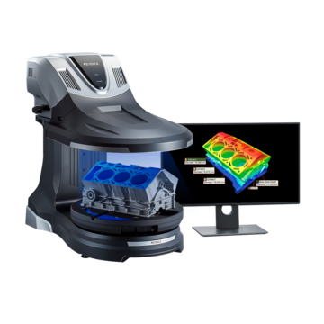
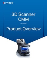
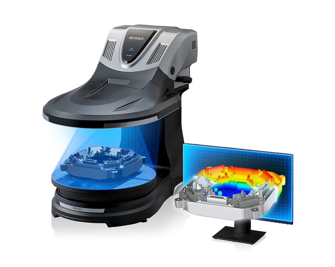
The VL-700 Series 3D Scanner CMM is equipped with the world’s first fully automatic CAD conversion function. From scanning to STEP file output, this scanner handles everything automatically. There is no need to go through specialized conversion software to obtain data in a format accessible by CAD software, which eliminates these steps from the work procedure. Furthermore, the newly developed high-resolution transmitter and receiver lenses and WDR (Wide Dynamic Range) CMOS sensor offer twice the detection ability of conventional models. True-to-life scanning makes it possible to obtain accurate 3D data with shape and color information. Using the comparison fitting algorithm, CAD data and coordinates can be used to perform comparative measurements.


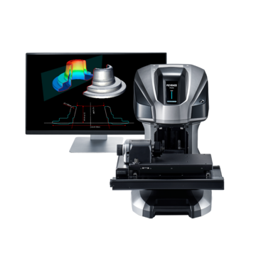
The VR-6000 optical profilometer performs non-contact measurement to replace stylus profilometers and roughness meters. This 3D profile system captures full surface data across the target with a resolution of 0.1 µm, enabling measurement of features that cannot be performed with probe-type instruments. The new rotational scanning greatly expands the measurement capabilities of the system. True-to-life cross section measurements can be performed with no blind spots. Wall thicknesses and recessed features can be measured without cutting or destroying the target. In addition, the HDR scanning algorithm provides enhanced scanning capabilities for instantly determining the optimal settings to capture high quality data, even on glossy and matte surfaces.


A 3D scanner is a device that acquires 3D coordinate data from a target and converts it into 3D digital data. There are two main scanning methods used by 3D scanners: contact scanning, where a probe or sensor comes into physical contact with a target to acquire coordinate data directly, or non-contact scanning, where a laser or other non-contact device is used to acquire 3D data.

How Contact-Type 3D Scanners Work
With a contact-type 3D scanner, measurement is performed by touching a probe or sensor to the target to acquire the 3D coordinates of the contact location, and those coordinates are then converted into 3D data. Although this is an older method, it offers accurate results because the coordinates are obtained from directly contacted locations. Also, because many targets can only be measured through contact, this type of scanner has been used in a wide variety of worksites. Although contact-type 3D scanners offer excellent measurement accuracy, measurement must be performed in a temperature-controlled environment, and measurement can take a long time, so measuring large targets and completely scanning complex shapes can be difficult or impossible.
How Non-Contact 3D Scanners Work
Non-contact 3D scanners measure targets using a laser or other light source, and the measurement results are converted to 3D data. There are two types of non-contact 3D scanners: those that use lasers, and those that use projected light patterns.
Scanners that use lasers irradiate a target with a laser beam, and the reflected light of the laser is then detected by a CMOS sensor or other device. The coordinates are then obtained by measuring the time difference and reflected angle of the light. On the other hand, scanners that use pattern light projections shine light onto a target in a striped or other pre-determined pattern, and a camera detects any displacement or distortion in the lines to determine the shape of the target.
Laser-based scanners offer detailed coordinate information, while pattern light projection scanners are known for their ability to quickly measure a wide area. These scanners are also ideal for use with targets that may change shape due to contact with a probe or other device. However, a disadvantage of these scanners is that the reflected light may change depending on the material and shape of the target, which can make it impossible to determine exact coordinate information. There may also be blind spots on the target where the camera cannot detect the light. Also, if the camera or projector used to detect the reflected light is positioned at an angle or misaligned, reading the exact shape of the target will be impossible.
With non-contact 3D scanners, coordinates and shapes are calculated from the position and angle of the projected light from the projector and of the camera detecting the light, or from the position of the laser and the CMOS sensor detecting the reflected light. This means the position of each component must be correct, so calibration is required when the equipment is moved or subjected to sudden shaking (such as from heavy machinery operating nearby) or thermal shock. With KEYENCE’s VL Series, calibration is as easy as placing the dedicated calibration board in the field of view and pressing a button. This makes it possible to immediately perform on-site adjustments as needed.

Laser scanning method
A: Laser beam B: CMOS sensor
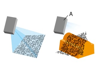
Pattern light projection method
A: Projector that emits patterned light
Structured Light Principle
KEYENCE’s 3D Scanner uses the structured light method to capture high-resolution 3D data. Structured light is emitted from the transmitter lens and projected onto the surface of the object. The reflected light is then detected by the receiver lens and will appear banded and bent based on changes in the topography of the surface. Triangulation is then used to calculate and measure the height of the surface. KEYENCE’s VL Series incorporates a newly developed high-resolution receiver lens and 9-megapixel wide dynamic range CMOS sensor that offers twice the resolution of conventional models, enabling even the most minute surface details to be captured. Additionally, the VL Series features a fully-automated smart stage and integrated camera that rotates the part while scanning, allowing users to capture a complete 360 degree scan of the sample without the need for placing alignment stickers.
Benefits of 3D Scanners
3D scanners can measure in both 3D and 2D with easy operation. Set-up and measurement operations are simple, so anyone can measure complex objects with high-accuracy. 3D measurement scanners can measure cross-sections, thickness, and perform GD&T measurements in a single scan.
With conventional measurement systems, many setup steps are required, such as fixturing, stage adjustments, and precise placement of the measurement target. However, with a 3D scanner, an operator is only required to place the target object on the stage and measurement can start right away. Additionally, because the entire surface is scanned, a 3D scanner can perform nearly limitless measurements, including measuring the highest and lowest points across a surface, distances between lines, and distances between circles or other features.
Target objects can be compared directly against 3D CAD data, or against measurement data from a similar part. Comparing target measurement data can help verify conformity and identify defects.
Comparing a 3D scan against the object's 3D CAD data enables visualization of any differences between the final product and the design. Objects that are difficult to measure with conventional approaches, such as parts with free-form shapes or complex geometries, can be quickly compared against CAD data to instantly visualize any areas the part is out of tolerance. Additionally, different sets of measurement data from the same product can also be compared, which allows for capturing changes in the shape of the product before and after use, or for identifying why one part may be working while another is failing.
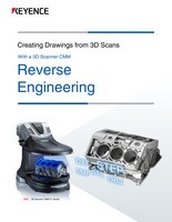
Reverse engineering analyzes existing products to reveal their specifications, components, and design. A 3D scanner can recreate the shape of a product with high data quality, enabling drawings to be quickly made for already existing products.
Reverse engineering helps determine the manufacturing method and working principle of a product by analyzing the product itself or its components. A 3D scanner can accurately analyze, dimension, and create drawings or DXF files of even complex shapes and products. With the ability to quickly measure objects regardless of their complexity, 3D scanners are optimal measurement systems for reverse engineering.
In recent years, additive manufacturing using 3D printers has become increasingly popular. Similarly, 3D scanners have become increasingly used within the 3D design and printing process due to their ability to quickly create digital models of existing objects and parts. This process of using existing parts to create new designs is referred to as reverse engineering, and can save both time and effort in the following situations:
1. A customer has requested a part design but does not provide a drawing. 2. The customer provides only an existing part for reference, but not the design file or drawings. 3. You are required to make a part that is different from the drawing but has the same general shape as a proven part. 4. Only paper drawings exist of old parts.
3D Scanner Case Studies
Stamping Industry
Metal and plastic materials have plasticity and elasticity that affect the way they are worked, and as such, making industrial products to design specifications can be incredibly difficult. To assess the shape of a product, the entire part must be scanned with a 3D scanner.
With a 3D scanner, measurement of deep drawn products, spring back analysis, and plate thickness evaluation can be easily performed. Profile measurement of deep drawn products can be done by visualizing the part against its CAD data, while spring back can be analyzed by measuring the difference from cross-sections. In addition, hand tools cannot capture the thickness of a bent part or changes in thickness caused by metalworking, but a 3D part scanner can capture the rate of reduction of plate thickness across the entire part.
For the 3D Scanner for the Stamping Industry Application Guide, click the button below.
Injection Molding Industry
Injection-molded parts can be difficult to measure due to their freeform geometries and can deform when measured with contact tools. 3D Scanners allow for a wide range of measurements to be performed on molded products, including radii, flatness, and curvature. Warpage caused when the part is removed from its mold can be quickly and accurately measured across the entire part. Additionally, samples from different molds can be scanned and the data superimposed so differences can be instantly understood.
For the 3D Scanner for the Injection Molding Industry Application Guide, click the button below.
Casting Industry
Due to the limited number of data points captured, measuring systems that collect point data may overlook non-conformities that would otherwise cause measurements to fall outside of dimensional tolerances. A 3D scanner can be used to acquire scan data for the entire product to evaluate its true shape.
With a 3D scanner, it is easy to evaluate the shapes of the fins of alternators and heat sinks, as well as to measure the positions of electrical parts. When evaluating the shape of an alternator, the CAD data can be directly overlayed on the 3D scan to identify any non-conformities. Additionally, the fins of a heat sink can be virtually cut into cross-sections to measure their pitch and height, without destroying the part.
For the 3D Scanner for the Casting Industry Application Guide, click the button below.
Pressed Parts: A Method for Measuring the Thickness of Drawn Products
Because defects in wall thickness and minimum thickness affect the strength of drawn products, highly accurate and quantitative 3D shape measurements are necessary. However, it is very difficult to accurately measure with minimal variation between operators when using coordinate measuring machines or calipers. The easy-to-use VL Series 3D scanner CMM accurately captures the entire 3D shape of a surface without contacting the target, allowing users to automatically measure thickness and minimum thickness. Furthermore, cross-sectional shape displacement can be checked with profiles, allowing for the identification of issues such as springback and the quick implementation of corresponding countermeasures.
Cast Products: A Method That Allows Anyone to Measure Cast Products Easily and Accurately
3D shape analysis is vital in quality assurance because cast products with dimensions outside the tolerance range can affect the strength and operation accuracy. Using a coordinate measuring machine that captures one point at a time requires a lot of time and a high level of skill. On the other hand, the VL Series 3D scanner CMM captures the data in minutes at the click of a button, enabling highly accurate measurement of surface strain and complex 3D shapes. Easy quantitative evaluations are made possible by visualization of uneven surfaces with color maps, capturing of profile data, 11 types of GD&T measurements, and comparisons with 3D-CAD data.
Plastic Molded Parts: A Method of Accurately Measuring Plastic Molded Fitting Parts
Plastic molded parts with complex shapes conventionally required multi-point measurements with coordinate measuring machines and calipers. It not only required a lot of time and a high level of skill but also had the problem of measurement variations when performing contact measurements due to the low hardness of plastic. The VL Series 3D scanner CMM can complete a 3D scan of the plastic molded part on the stage in minutes without touching the target, allowing for highly accurate measurements. Uneven surfaces can be visualized with color maps, specified cross sections can be measured in a non-destructive manner, and differences between 3D-CAD data and the target can be visualized. Defects such as subtle warpage, waviness, strain, and short shots can be easily identified, allowing for prompt implementation of countermeasures.
Cut Products: A Method for High-accuracy Measurement of Free-form Surfaces on Cut Products
The 3D shapes of impeller blades, propellers, and spiral gears—cut products having free-form surfaces—are difficult to measure quantitatively with coordinate measuring machines, tooth thickness calipers, and tooth thickness micrometers. The VL Series 3D scanner CMM can complete a full 360° scan of the target in minutes and with simple operations, allowing for highly accurate and quantitative measurement. Specified locations can be measured in the specified manner, for example, the thickness, pitch, curved shapes, and GD&T of impeller blades. Verification against 3D-CAD data is also possible. Additionally, the profile of the specified cross section can be measured in a non-destructive manner when measuring the over-pin dimension of a gear.
A Method of Optimizing 3D Measurement in Reverse Engineering
In reverse engineering, where design drawings are reproduced from actual products and parts, it is necessary to measure the shape of the entire target with high accuracy. The VL Series 3D scanner CMM scans the target in a non-contact manner. It captures 3D shape data with high accuracy, simple operations, and no positioning or leveling. Because data can be combined, surfaces that were not fully captured at the first scan can be scanned and added at a later time. Furthermore, non-destructive measurement and analysis of cross sections as well as output as DXF data are possible. This all adds up to allow dimensions to be quickly evaluated and converted to drawings.
A Method for Improving the Efficiency of 3D Measurement for Digital Archives
When building a digital archive, a tangible fixed asset, the shape and color information of the original items must be measured and recorded in as much detail as possible. Non-contact and fast 3D scanning with the VL Series 3D scanner CMM is useful in capturing the data of these valuable and fragile original items. The cross-sectional shape of the specified location can be measured in a non-destructive manner from the 3D shape data and converted to DXF data or an STL file. Also, the color information can be captured with the built-in, large, high-resolution CMOS camera. The data necessary for building a digital archive can be captured quickly, with high accuracy, and with simple operations.
Frequently Asked Questions About 3D Scanners
3D scanning accuracy normally ranges between 10 - 100 microns. 3D scanners typically excel at measuring large parts that do not contain small surface features, as the accuracy isn't high enough to obtain high-resolution surface shape data. With the VL Series, high-magnification lenses can be used to capture up to 16 million data points on the surface of a part, ensuring even small features or targets can be accurately measured.
3D scanning is a non-contact form of measurement that captures the three-dimensional shape of a target object through the use of a projected light source. Optical scanners typically project a white or blue striped pattern onto the target object, and measure the displacement of the lines to construct the 3D model. A 3D laser scanner projects a laser onto the target surface, and measures the time required for the laser to return to the light-receiving element to map the surface of the part. Both white/blue light 3D scanners and 3D laser scanning systems can be used to perform measurements
3D scanners are used to acquire data on target objects so the user can visualize and measure the surface of the object. Some 3D scanners allow scanned objects to be directly compared against their CAD model, so users can quickly understand how a manufactured part differs from the design. 3D scanners are used in quality control and research and prototyping across many industries, including stamping, molding, casting, and electronics.
Depending on the end goal of the user, the use of a 3D scanner can typically require multiple different types of software to be used.
Data acquisition: Software is needed to operate and control the scanner during the pre-measurement and data acquisition phase. Typically, this software is unique to the scanner being used, and is often created by the manufacturer of the 3D scanner.
Data processing: After the data is captured, it needs to be processed in order to become usable information. During this phase, advanced algorithms analyze the collected measurements, align multiple scans (if applicable), and reconstruct the object in a virtual space. This processing stage also typically includes steps for noise reduction, data interpolation, and the creation of a detailed point cloud representing the scanned target. Data processing software is often packaged together with data acquisition software.
3D Measurement: Once a virtual model of the physical object is created, users are able to perform all types of measurements, including dimensional checks, cross-sectional measurements, GD&T, thickness measurements, and are sometimes even able to overlay the scanned model with its CAD model to quantify differences. The 3D measurement software can be created by the manufacturer of the 3D scanner, however it is also common for measurements to be performed within a 3rd party software.
CAD Conversion: 3D scanners are commonly used for reverse engineering, and converting the point cloud data to a usable CAD model is a crucial step in the reverse engineering process. During this phase, the point cloud data is converted to a Series of polygons that define the shape and surface details of the object. In order to make the data easier to work with in CAD software, the polygons need to be grouped together to create geometric shapes that the CAD software can easily recognize. Depending on the sophistication level of the software, this can be a time-consuming process. Finally, the 3D model can then be output in a file format that is compatible with the modeling software being used.
KEYENCE’s VL 3D Scanner combines the functions of data acquisition, data processing, CAD conversion and output, and 3D measurement software into one easy-to-use package. Users can capture data, perform 3D measurements, convert the data to a CAD model, and output it for use in their favorite modeling software without needing to change programs or purchase multiple different licenses.
When considering a 3D scanner, the scanner must be able to meet the specifications necessary for producing the desired data. The following section introduces four key points to consider when looking to introduce a 3D scanner.
Measurement Method
3D scanners can either be contact-based or non-contact. Contact-type 3D scanners are used for inspecting and measuring targets when high accuracy is required. Non-contact scanners can quickly acquire 3D coordinate information by scanning over a wide area all at once, even for targets with complicated shapes. Because of this, non-contact scanners are also used for scanning large structures and cultural assets that cannot be touched directly.
Accuracy
When it comes to 3D scanner performance, accuracy is an important aspect to consider, not only in terms of the coordinate acquisition accuracy but also in the number of scan locations with more complicated shapes. Each manufacturer follows its own standards for accuracy, including repeatability and minimal variation between point groups, so checking whether the accuracy of a device is appropriate for the application is important. KEYENCE’s 3D scanners also offer various functions for visualizing differences from actual products, including CAD comparison and comparative measurement.
Resolution
Scanners with high resolution can capture more informative, accurate, and realistic 3D data. However, data loads increase at higher resolutions, so processing takes longer. This means users need to decide whether to prioritize speed or resolution. Still, some products may offer the same resolution but faster data processing speeds, which can help improve operation rates.
Ease of Use
3D scanners can be either stationary or handheld devices. Stationary scanners are fixed in place and do not shake during scanning, ensuring accurate coordinate information is obtained. These devices are used for more time-consuming scanning processes. With a KEYENCE 3D scanner, however, scanning can be started at the press of a button, while settings can be configured just by selecting the necessary items.
On the other hand, handheld scanners can be used in any location, but these devices are more prone to camera shake because the probe must be held by hand during scanning. The greater freedom of movement also makes it possible for users to obtain more detailed coordinate information.
In addition to ease of use, a product’s after-sales support is also an important factor for ensuring continued use. KEYENCE is dedicated to providing a comfortable environment for anyone using its 3D scanners, including providing operation support, offering product inspections, and lending equipment as necessary if a malfunction occurs.
We have led the way in industrial automation and inspection equipment since 1974. Our commitment to advanced technology and meeting our customers' needs have elevated us to a leadership position in the marketplace. If you're ready to buy 3d scanners from the recognized leader in the field, browse our catalog and get in touch today.

The 3D Solution Library is an informative site that includes examples of common profile measurement problems as well as the latest solutions for a wide variety of industries, processes, and operations.
The latest 3D scanners can easily take measurements that were impossible with hand calipers, profile measurement systems, and CMMs. This brochure introduces tips for solving measurement problems using 3D scanner functions with common targets as examples. A must-read compilation of applications for anyone struggling with dimensional measurements.