Accurately Measuring Bending Radius in Sheet Metal Working
Bending of metal materials utilizes the ductility which is unique to metals, and is a machining method which is commonly used in sheet metal working and other metal working.
Bending is closely related to the strength of a material; therefore, bending to an inappropriate radius can cause deformation, reduced strength, and damage. This is why measurement of the bending radius can have a large effect on quality.
This page uses sheet metal working as an example of metal working to explain basic knowledge of bending radius, how to calculate it, countermeasures to defects, problems in conventional bending radius measurement, and the latest measurement method that dramatically improves work efficiency and accuracy.
- Bending Radius
- Bending in Sheet Metal Working
- Stress Occurring during Bending in Sheet Metal Working and Related Precautions
- Calculating the Developed Bending Length Using the Bending Radius
- Cracking Countermeasures and the Minimum Bending Radius
- Problems in Conventional Bending Radius Measurement
- Solution to Problems in Bending Radius Measurement
- Summary
Bending Radius
The bending radius is the radius from the start point of the bend to the center of the bend in plastic working of a metal or other sheet, pipe, or rod by pressing or rolling.
Each material has a limit for bending without fracture which is determined by its thickness or diameter. This is called the minimum bending radius. A bending radius must be set appropriately for the bend location and the application. Resisting stress caused by bending can also affect the finished bending radius.
Bending in Sheet Metal Working
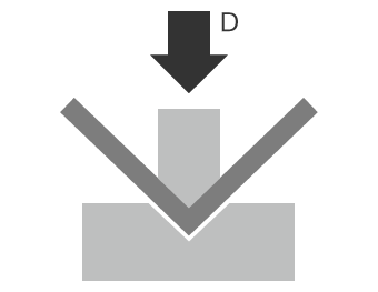
One typical process where bending radius is important is sheet metal working. A common method of sheet bending uses a “press brake” that presses the sheet between the upper die called the punch and the lower die. In addition to the V-dies shown in the figures below, various types of dies are used according to the bending shape and material. These include radius dies that bend the sheet in a gentle curve and U-bend dies that bend a sheet at two points simultaneously in one stroke.
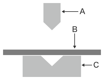
- A
- Punch (upper die)
- B
- Sheet metal
- C
- Die (lower die)
- D
- Pressing
When bending thick sheets, some press brakes may use a radius punch, or may use a deep V-die (lower die) even for ordinary V-bending. When bending to a large bending radius, the sheet may be shifted little by little during bending. A punch called a “radius ruler” may be used to measure the radius.
Stress Occurring during Bending in Sheet Metal Working and Related Precautions
The following stresses are generated in a bent sheet. Depending on the thickness and hardness of the worked material, these stresses may have a large effect on the bending radius.
- A
- Bending radius
- B
- Compressive stress
- C
- Tensile stress
- D
- Neutral axis
- • Compressive stress
- The inner side of the sheet thickness neutral axis is compressed, generating a force in the material which resists the compression.
- • Tensile stress
- The outer side is stretched in the tensile directions, generating a force in the material which resists the tension.
- * In the thickness direction cross-section, the line running through the middle of the sheet where none of these forces is acting is called the neutral axis.
When the pressed material is removed from the dies, the material may springback due to the residual compression stress and tensile stress, widening the bending angle of the bent part. This is called springback, and it is more likely to occur in hard materials because these materials tend to generate higher compressive stress and tensile stress. Such materials need to be overbent to an angle narrower than the intended final angle.
The amount of springback varies depending on the sheet material and thickness, and thick sheets tend to have the neutral axis displaced inward. This is why it is important to identify the amount of springback and set appropriate metal working conditions.
Calculating the Developed Bending Length Using the Bending Radius
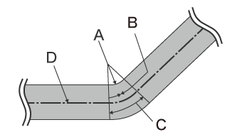
The developed bending length is required in order to allow for stable bending. It can be estimated by obtaining the distance from the bending radius surface to the neutral axis. As the straight parts A and B are not changed by bending, use the actual values.
The neutral axis shift ratio (λ: lambda) at a bent point differs depending on the material thickness, hardness, bending angle, and internal bending radius. The neutral axis is believed to be located at a position that is approximately 20% to 45% of the thickness from the inner surface. In the workplace, values based on experience are used. The following is the formula for calculating the developed bending length.
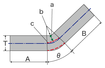
- a
- Distance from the bending radius surface to the neutral axis
- b
- Bending radius
- c
- Neutral axis at the bent part
L = A + B + (R + T x λ) x 2n x θ / 360
L = Developed length
A, B = Length of parts not subjected to bending stress
R = Internal bending radius
T = Thickness
θ = Bending angle
λ = Neutral axis shift ratio (%) * Value based on experience
Cracking Countermeasures and the Minimum Bending Radius
Problems occurring during bending include defects such as cracking and tearing at the bent parts. Attention needs to be paid to the direction in which the material is worked because these defects are closely related to the rolling direction of the material. Cracking and other defects are more likely to occur when the material is bent parallel to the rolling direction. These defects are particularly likely in stainless steel materials and aluminum materials.
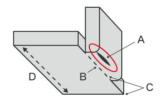
- A
- Location that is likely to crack
- B
- Bending line
- C
- Contour line aligned with the bending line
- D
- Rolling direction parallel to the bending line
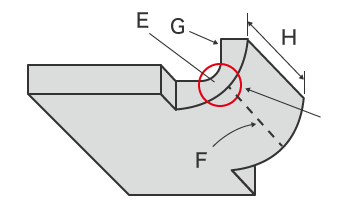
- E
- Reduced sheet thickness at the bent part
- F
- Bending line
- G
- Fracture cross-section
- H
- Bending width less than eight times the sheet thickness
To prevent these defects, it is necessary to observe the minimum bending radius. However, the minimum bending radius varies depending on the material, sheet thickness, die, and other factors, making it difficult to calculate the correct value using a mathematical formula. Therefore, it is necessary to set the minimum bending radius based on experience or testing, and incorporate countermeasures to prevent cracking in the design and metal working.
- Set the bending line perpendicular to the rolling direction.
- Select a material which has high ductility.
- Select a material which has small crystal grains, or reduce the size of the crystal grains by heating.
- Displace the bending line from the sheet contour line to make it less likely that cracking will be caused by insufficient elongation when the sheet is bent.
- When a punched sheet is bent, the sheared surface elongates more easily without cracking than the fractured surface. Bend it with the shear droop side on the outside.
- Use a bending width that is at least eight times larger than the sheet thickness.
While it is important to give attention to the design and materials to prevent cracking and other defects, making sure the material is bent to the appropriate shape within the tolerances is critical. The next section explains methods of measuring bending radius, the problems with each method, and a solution to these problems.
Problems in Conventional Bending Radius Measurement
When higher bending accuracy is required, it becomes more difficult to completely prevent defects even when the material, design, and press dies are chosen correctly. Cracking, chipping, and defective shapes (such as a wider bending radius caused by springback) can lead to problems including lower yield rates, as well as poor quality and breakage of products.
Therefore, it is very important to accurately measure and inspect the shapes of as many bent products as possible during die trials and when the material or bending conditions are changed. When measuring the bending radius, coordinate measuring machines (CMMs), optical comparators, and other measuring instruments are used in addition to handheld tools such as radius gauges. However, there are various problems in bending radius measurement using these conventional measuring instruments.
Problems in bending radius measurement using a coordinate measuring machine
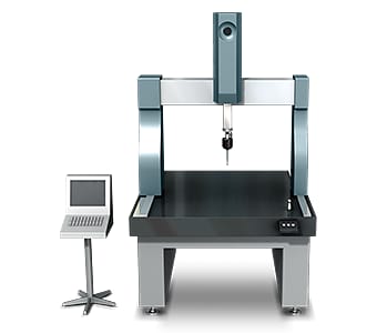
For ordinary measurement of a bent part using a CMM, it is necessary to contact multiple points on the measurement target surface with the probe tip.
When the measurement area is large, measurement accuracy can be improved by increasing the number of measured points to collect more measurement data.
However, this involves the following problems.
- Measurement takes much time. Measurement requires much time and effort, especially for high accuracy measurement of a wide area because of the many points that need to be measured.
- When a small workpiece has recessed parts or a complex shape, or small bending radius, it can be difficult for the probe to make contact.
- Measurement requires skill and experience. Only limited operators are capable of measurement, resulting in inefficient measurement work.
- Tabulating the measurement data and calculating values also requires expertise, skills, and many man-hours.
Problems in bending radius measurement using an optical comparator
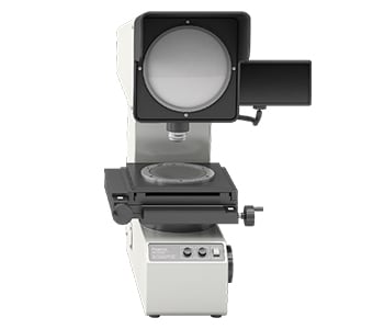
An optical comparator is a type of optical measuring instrument, with measurement principles similar to that of an optical microscope. This measuring instrument emits light underneath the target, projecting the profile onto a screen.
Some large optical comparators have a screen with a diameter of more than 1 m (3.3′). These optical comparators can superimpose a projected 2D profile on an enlarged drawing to visually identify differences between them, however this requires much labor and skill.
Measurement using an optical comparator involves the following problems.
- Leveling is required when installing the target. Some sample shapes cannot be measured.
- Because bent targets have three-dimensional shapes, it is impossible to determine the conditions of the entire bent surface using a 2D profile projected from the side of the target.
- The measurement method varies slightly with different operators, and variation in the measured values is likely. Differences between the projected dimensions and the drawing cannot be obtained in numerical form, and the profile shape must be transferred to tracing paper, making it difficult to store and compare the data.
In all, this method involves many problems; not all workplace operators can accurately measure profiles and not all parts can be measured. Along with that, some samples will need to be cut due to the target shape.
Solution to Problems in Bending Radius Measurement
Conventional measuring instruments are limited to capturing points or lines or can only compare 2D profiles. This yields low measurement reliability and makes it difficult to obtain numerical values.
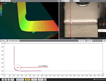
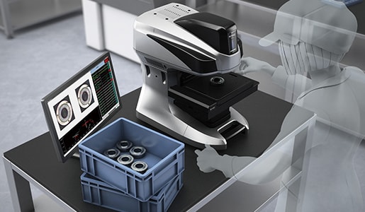
To resolve these measurement problems, KEYENCE has developed the VR-Series 3D Optical Profilometer.
The VR Series accurately captures the 3D shape of the entire target surface without contacting the target. This tool allows user to take accurate and repeatable measurements in as little as 1 second by simply by placing the sample on the stage and clicking a single button. The system automatically sets the measurement range and conditions, ensuring accurate quantitative measurements without variations between users. This section introduces some specific advantages of the VR Series.
Advantage 1: 3D shape of an entire surface can be captured in as little as 1 second.
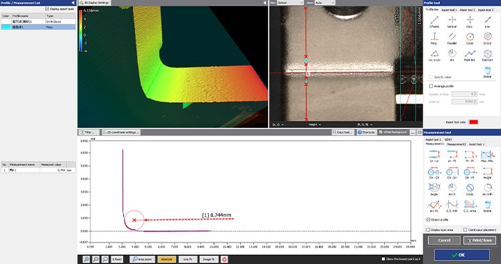
The VR Series instantaneously acquires surface data (800,000 data points in one scan) in as little as one second. It allows accurate measurement and evaluation of the maximum and minimum surface irregularities across the entire bent part.
The VR Series can also measure profiles at specific locations. Even after measurement, profiles of different parts can be acquired from the 3D scan data without scanning the target again.

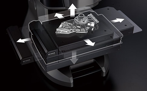
Advantage 2: Easy-to-use operation for accurate and repeatable measurement from user to user.
3D shape measurement can be performed easily just by placing the target on the stage and pressing a button. Because automatic position adjustment is possible based on target feature data, strict leveling or positioning is not required. This series also includes the industry’s first Smart Measurement function that automatically configures the measurement range and moves the stage according to the target size. This eliminates the work required to set the measurement length and Z-range.
The wide variety of assist tools allows simple setup of the desired measurement contents.
In addition to easy configuration, the assist tools allow the system to be operated by even novice users, making it possible for anyone to measure shapes quickly and accurately. As a result, the number of samples can easily be increased not only for prototypes and trials, but also for measurement and inspection of products.


Summary
The VR Series can measure 3D target shapes accurately and instantaneously by high-speed 3D scanning without contacting the target. Even the radius of a bent part, surface irregularities, and other difficult targets can be measured in as little as one second. The VR Series solves all the problems involved with conventional measuring instruments.
- This series is capable of measuring cross-sections without cutting the target.
- This eliminates variation resulting from human factors, making true quantitative measurement possible.
- Without the need for positioning or other preparation, measurement can be done simply by placing the target on the stage and pressing a button. This eliminates the need to assign a specialized operator for measurement work.
- Because 3D shapes can be measured easily at high speeds with high accuracy, a large number of samples can be measured in a short time. This is useful for quality improvements.
This system also allows comparisons with past 3D shape data and CAD data, as well as easy data analysis such as distribution within tolerances. It can be used effectively for a wide range of purposes including product development, manufacturing trend analysis, and sampling inspections.
