
CODE READING
LASER MARKING
Risk of insufficient reading stability due to inappropriately sized codes
Differences in surface conditions between resin materials purchased from different companies
Differences in marking direction and reader mounting angle between testing and actual installations
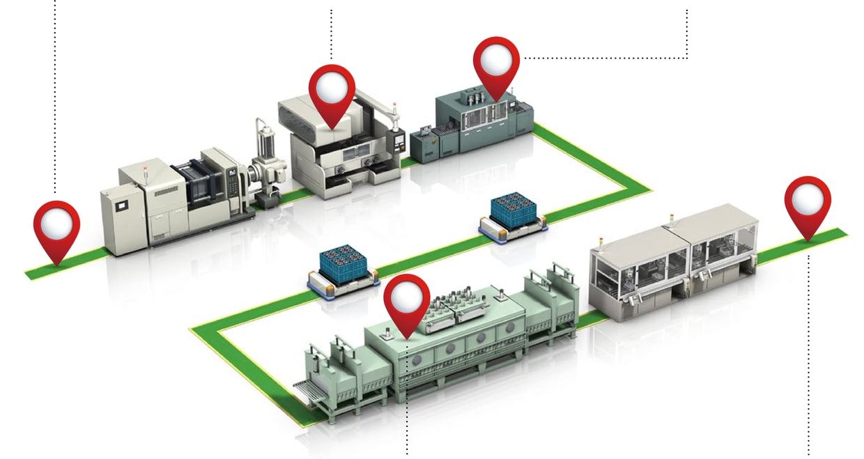
Changes in code reading rate before and after plating, during repeated firings, etc.
Matching level characteristics and monitoring of code quality and device status trends
When it comes to 2D codes, oftentimes the design department will only specify the code size and data volume. However, creating a code simply to meet such specifications opens the door to potential problems later on during operation.

For some code types, the module size may be too small for the amount of information being implemented, resulting in unstable reading. Here at KEYENCE, we suggests the most suitable type of code and shape depending on the target.
Module size
= 0.63 mm
Module size
= 0.63 mm
Module size
= 0.63 mm
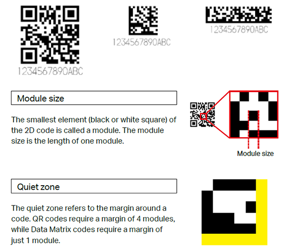
An alternative approach is to mark on patterns while minimising the damage to internal circuits. This improves readability for applications that require very small markings with limited free space with conventional systems. This ensures the code size is appropriate for the target, while stabilising the reading rate.
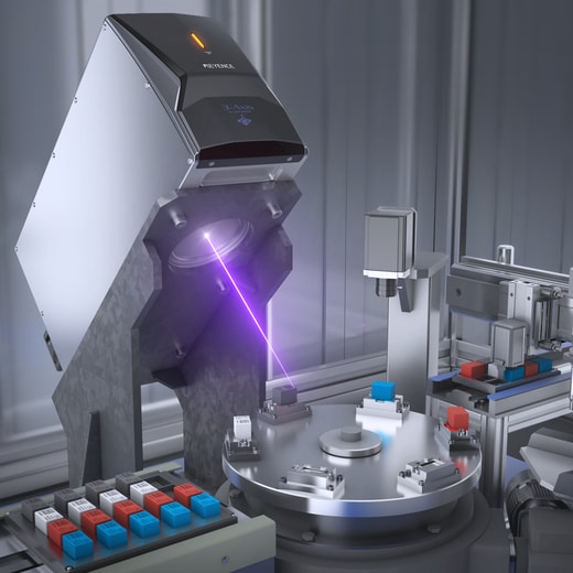
Even when using similar materials, surface conditions may vary between suppliers, leading to different marking conditions and the possibility of unstable reading in some situations.
KEYENCE offers advice on marking and reading conditions while taking such risks into account.
Supplier A
Supplier B
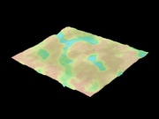
Uneven surfaces and marking results

Read result
[Code reader] *SR-X300 Series
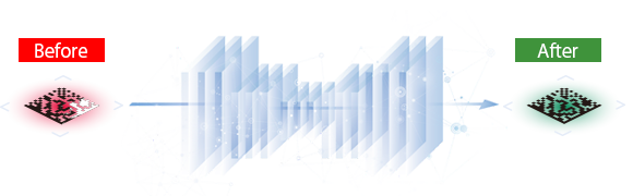
Optimized specifically for code reading, the built-in inference-specific AI chip was created through learning of a database of over 100,000 images. This results in dramatically improved code reading performance.
[Laser marker]
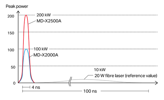
Combining a high peak power with a short pulse duration of 4 ns ensures highly stable high-contrast marking that is not affected by variations in the surface conditions of the material.
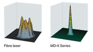
The figure on the right compares the beam power distribution of the MD-X Series and a conventional fibre laser. The MD-X Series produces a laser with a higher peak power and a shorter pulse.
In some situations, the test environment before purchasing differs from the actual production line environment. This results in a risk of unstable marking and reading results due to variations in product marking orientation and reader mounting angle compared to test conditions.
Pre-installation testing:
Perpendicular orientation of hairline metal surface and marking
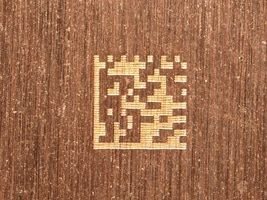
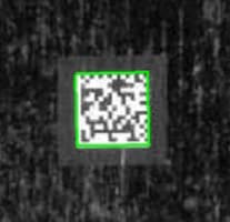
Contrast is high due to a significant difference between the amount of light reflected from the background and from the marked code.
Actual production line:
Parallel orientation of hairline metal surface and marking
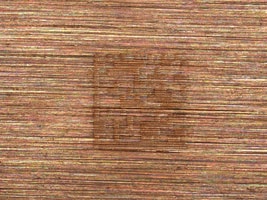
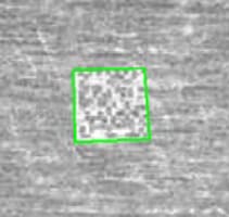
Contrast is low due to minimal difference between the amount of light reflected from the background and from the marked code.
[Code reader]
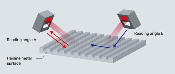
Reading codes on hairline metal surfaces can be unstable because the reflection angle of the illumination light changes. As shown below, the amount of reflected light changes between reading angle A—perpendicular to the hairline metal surface direction—and reading angle B—parallel to the hairline metal surface direction—resulting in a different reading stability.
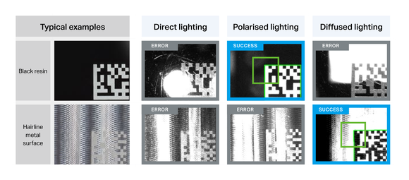
Built-in 3-way lighting (direct, polarised, diffused) * SR-X300 Series
[Laser marker]
With 11 marking patterns and 6 base patterns to choose from, KEYENCE laser markers can reduce the effects of hairline metal surfaces when marking 2D codes.
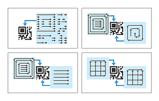
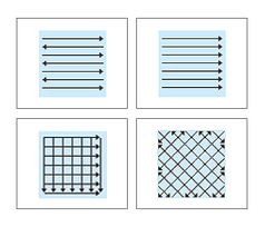
The code is marked in a circular pattern to reduce the effects of the hairline metal surface and increase reading rate stability from any angle.
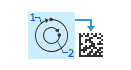
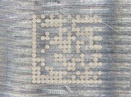
Marking image
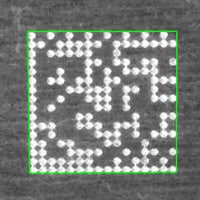
Read result
Surface processing that changes the marking can result in reduced reading stability.
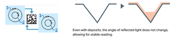
Surface treatment processes may unintentionally damage the modules as deposits accumulate in the concave areas of the code. This will change the way light hits the code, reducing the reading stability.
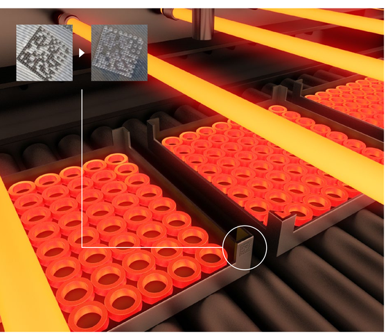
Before heat treatment
After heat treatment
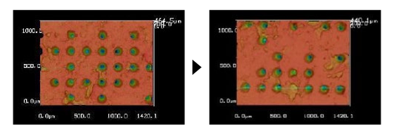
In some cases, codes on targets that have undergone heat treatment have substances burned into the modules, causing unstable reading.
Before plating
After plating
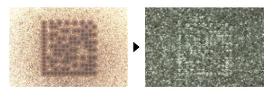
Plating can sometimes cause unstable reading by changing the colour of the material surface or changing the code’s engraving amount.
[Code reader]
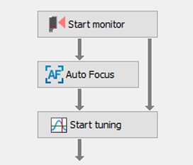
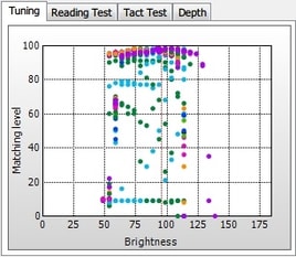
KEYENCE offers simple setup software that takes into account the various changes of a marked code to ensure optimal reading performance for stable operation.
Reading conditions are also taken into consideration during processing, with the results being used to determine if the marking conditions are suitable for mass production.
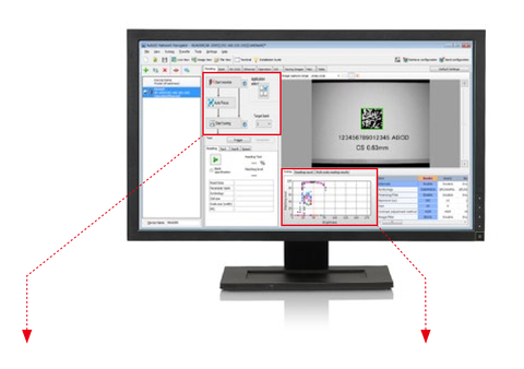
Easy 3-step configuration
Tuning
[Laser marker]
KEYENCE proposes marking conditions that are not easily affected by changes in surface conditions by selecting laser marking patterns to optimise the method for engraving the code.
Before processing
After processing

Marking and reading conditions can change due to a variety of unseen factors. Simply confirming that a code is sufficiently readable is not enough. An error may suddenly occur one day, causing various problems that will need to be handled, and time will be needed for investigating the cause.
To prevent this, predictive maintenance should be performed by monitoring code matching levels and outputting an error if the level falls below a certain threshold.
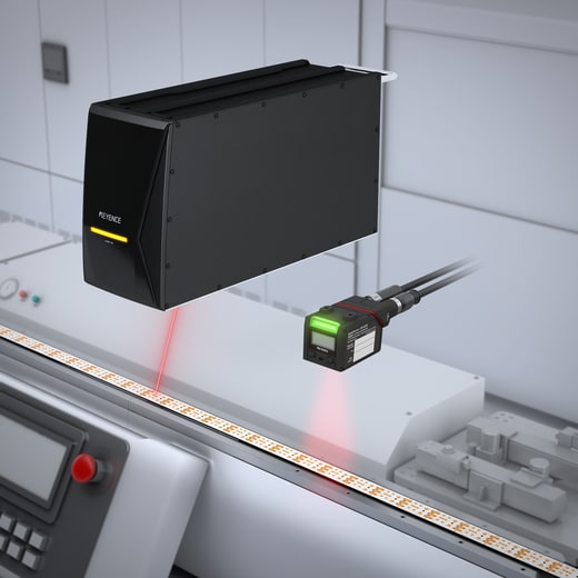
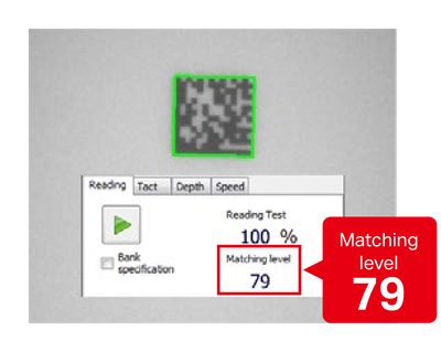
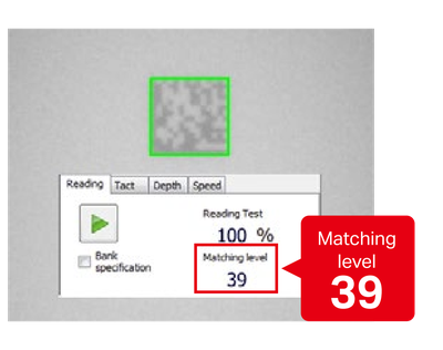
Whereas the reading rate only checks whether a code has been read, the matching level checks the reading tolerance of a code using a value between 1 and 100.
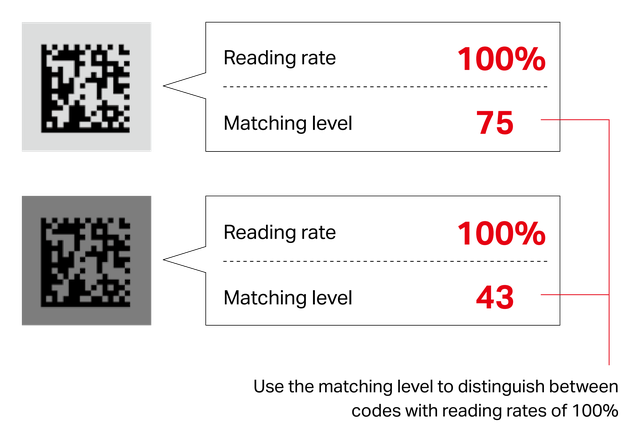
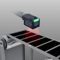
Monitoring matching level trends makes it possible to manage code quality and check the status of processing equipment in a production line.
Marking

Device A reader
Device B reader

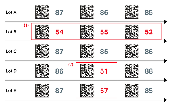
(1) Code deterioration → Check marking process and calibrate as necessary
(2) Equipment error → Check for misalignment of code reader, ambient light, and other factors
KEYENCE’s MD-X Series laser markers can monitor various trends that affect marking quality, including laser power and lens staining, without the need for other devices.
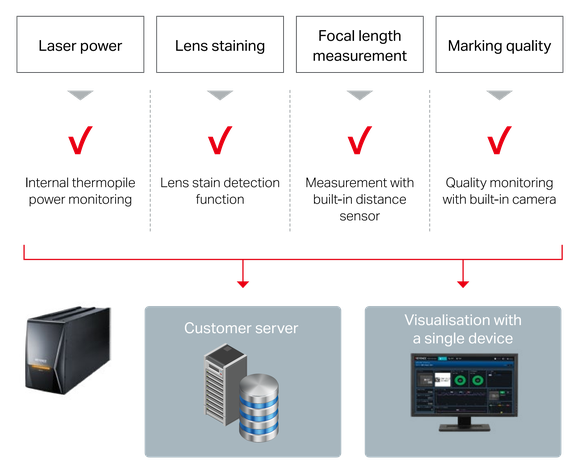
Ethernet-based data feedback to customer servers
Visualisation of data with Web Monitor function
If a problem occurs during operation, the top priority is to investigate the cause and restore the line as quickly as possible. Conventionally, this can take a long time because the laser marker manufacturer and code reader manufacturer are not the same. However, KEYENCE can respond quickly to any problem that may arise thanks to deep experience with both marking and reading.