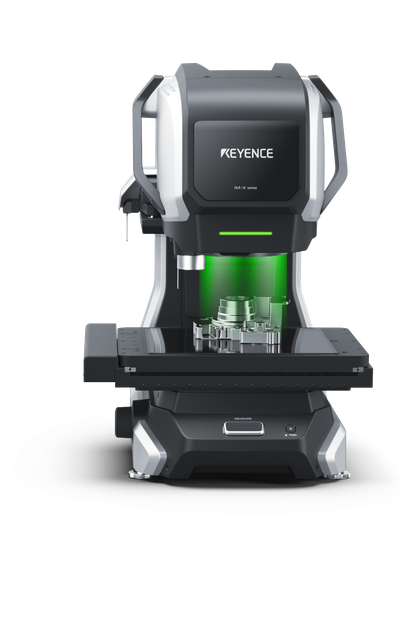
With the IM-X Series Image Dimension Measurement System...An all-in-one solution
A “New standard” in the manufacturing industry for hassle-free dimensional measurement
Measurements Performed in Seconds
Measurements of up to 5000 dimensions can be completed in seconds. Drastically reduce the time spent on measurement operations.
Intuitive Interface That Anyone Can Use
Just pressing the Measure button allows operators to acquire repeatable measurement results. The on-screen procedure display also allows anyone to operate the system easily.
Measurement Results Are Automatically Recorded
Measurement data is automatically saved and managed as soon as a part is measured. Inspection reports can also be created with the push of a button.
NEW
Image Dimension Measurement System IM-X
Measurement examples
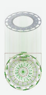
Pressed products
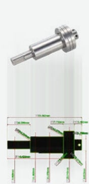
Lathe-processed product
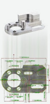
Machined parts
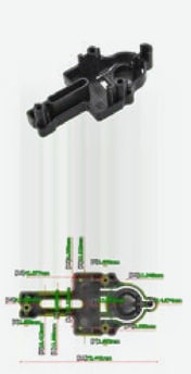
Resin molded products
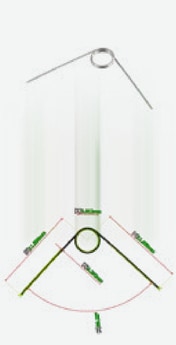
Springs
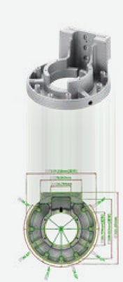
Die cast parts
Simply press the [MEASURE] button to execute measurement and display the result, as shown below.
Measurement example01
Large and tall parts can be measured all at once
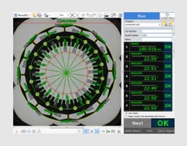
Measuring the outer diameter of a stamped part
Even for long shafts, the total length can be measured simultaneously through movement of the X stage. Up to 500 mm 19.69" × 400 mm 15.75" can be measured in a single operation.
Measurement method
- 1. The stage moves and captures three images; a composite image is then created.
- 2. The external circle is detected and the diameter is measured.
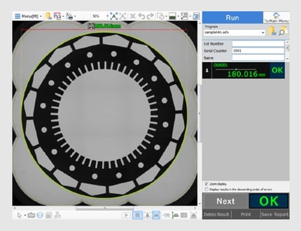
[Application example]
Measurement example02
Perform measurement using a virtual line in an instant
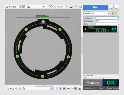
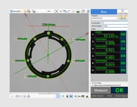
Measuring Pitch Circle Diameter
Pitch circle diameter is measured based on a circle connecting the center of the holes provided along the circumference. With an Image Dimension Measurement System, measurement can also be performed in an instant using a virtual line.
Measurement method
- 1. The target holes are detected and the center points identified.
- 2. A virtual circle passing through the center line is created.
- 3. The diameter of the virtual circle is measured.
[Application example]
Measurement example03
Even parts that deform through pressure contact can be accurately measured
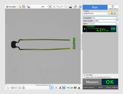
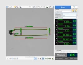
Measuring the bend of an electronic component lead
The pitch and position of the lead tip are measured. With an Image Dimension Measurement System, non-contact measurement can be performed without deformation.
Measurement method
- 1. The center line of the case is detected.
- 2. The midpoint of the lead tip is detected.
- 3. The pitch of the lead tip and distance from the case center line are measured.
[Application example]
Measurement example04
Measurement using multi-angle lightAllows stable measurement of the surface treatment and internal profile of resinmolded parts.
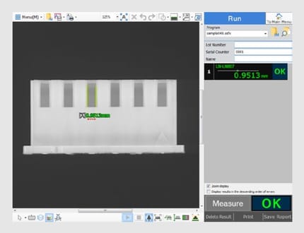
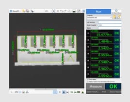
Measuring the profile of resinmolded parts
A projected image does not allow the surface treatment and internal profile of the part to be measured. Using internal ring illumination, a reflected image can be captured, making it possible to measure the profile of parts not visible with projection.
Measurement method
- 1. Ring illumination is irradiated.
- 2. Straight lines are identified on the reflected image.
- 3. The distance of the straight lines is measured.
[Application example]
Even at low-contrast areas along the edges of the resinmolded part, the height of illumination is altered so that a high-contrast image can be captured. This enables stable measurement of the reflected image.
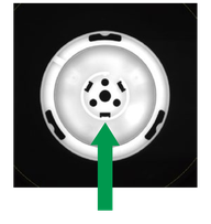
Image capture with multi-angle light
Contrast is low and edge detection is unstable.
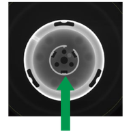
Image capture with multi-angle light
Contrast is increased by lowering the position of illumination, giving stable measurements.
Measurement example05
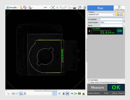
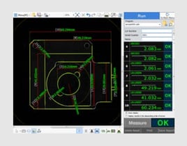
Measurement using slit ring illuminationThe curved surface of a machined part can be accurately measured
Measuring the curved surface of a machined part
Measurement method
- 1. Slit ring illumination is irradiated.
- 2. Straight lines are identified on the reflected image.
- 3. The distance of the straight lines is measured.
[Application example]
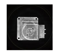
When the metal is illuminated from above, surface reflections lead to low contrast of the height difference and curved areas.
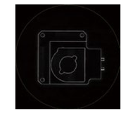
With slit ring illumination, the height difference and curved areas are illuminated with pinpoint accuracy from the side, thereby achieving high contrast and accurate measurements.
Inspection is now even simpler and more convenient
Measurement time is further reduced through 'multiple batch measurement'
With the IM-X Series simultaneous measurements of up to 1000 objects is possible. Since the position and orientation of the parts on the measurement stage are automatically detected, the user can place multiple parts anywhere on the stage and simply press the [MEASURE] button. All of the parts are then instantly measured.
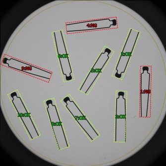
Quickly differentiate with OK/NG display.
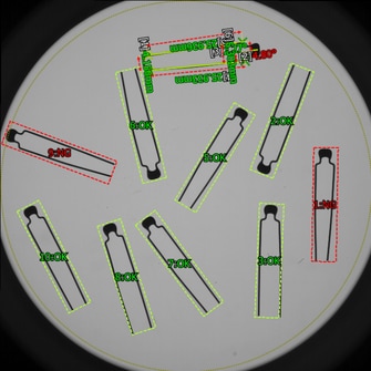
Easily identify NG spots.
Automatically finds the optimal lighting settings
Optimum lighting search function
It is often difficult to determine the correct lighting settings for a given feature. The optimal lighting search function simplifies this by showing you the actual images using different lighting techniques so you can simply select the one you want.
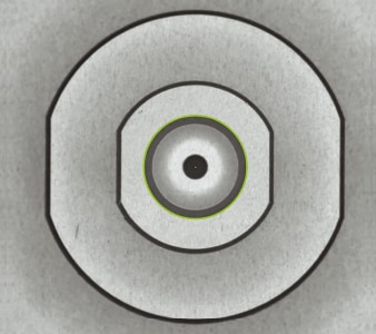
Select the feature to optimize
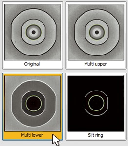
Select the settings from the automatically captured results
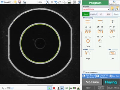
Measurements can be performed easily with the optimum settings
New Technology Allows Measurement of Features at Specific Heights
The low-measuring-pressure touch probe makes it easy to measure 3D machined shapes, including the perpendicularity of the top and side surfaces and the angle of slopes, which were difficult to detect with conventional measurement detects. It can also be used with commercially available styluses, allowing accurate measurement of deep holes and narrow grooves.
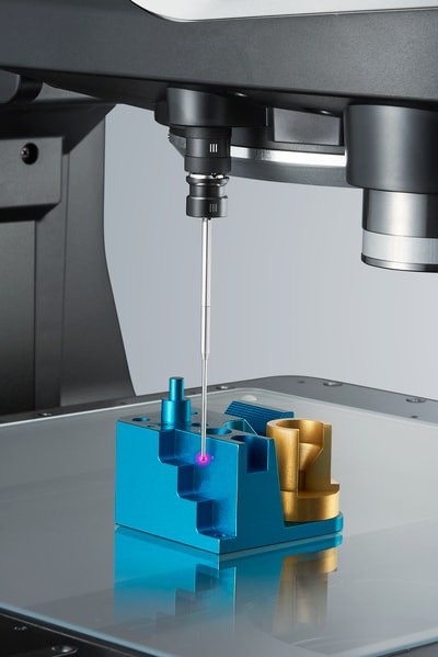
Low-pressure measurement touch probe
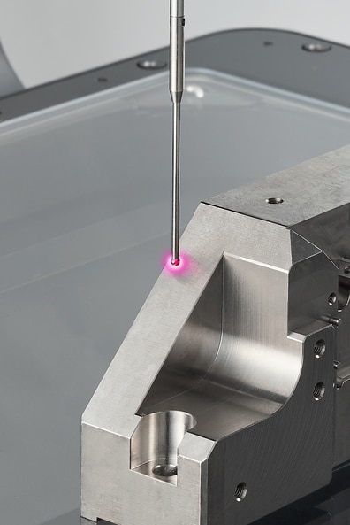
Can approach sloped surfaces
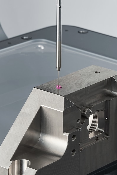
Small-diameter stylus that fits into small holes
Accurate measurement for small, light parts even without fixturing
Conventional contact-type measurement systems use a strong measuring pressure that can cause misalignment due to the pressure applied to small and lightweight parts. The low-measuring-pressure touch probe uses an ultra-low measuring pressure of 0.015 N to accurately take measurements without the hassle or cost of securing the part using a jig. This also eliminates concerns about deformation when flexible parts are measured.
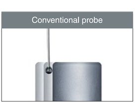
Pressure causes the part to move
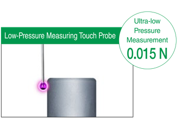
Detection is possible without affecting the part
Measurement systems that do more than "measure"
'Trend management' as a productivity improvement tool
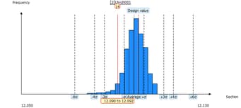
Histogram settings can be freely changed
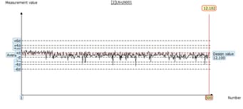
Trend graphs show product trends at a glance
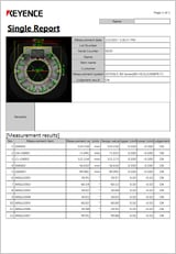
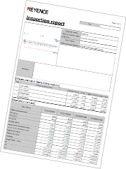
Easily create reports such as inspection reports