REWRITING THE BOOK ON DIMENSIONAL MEASUREMENTS Dimensional Measurement
Time-Saving Dictionary
■ Image Dimension Measurement System IM-X Series
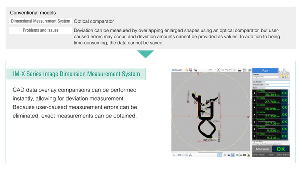
The IM-X Series Image Dimension Measurement System uses captured images to provide measurement at multiple specified locations in just a few seconds, all by simply placing the target on the stage and pressing the measure button.
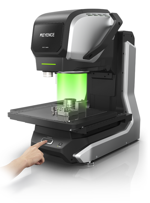
Offering a solution to any dimensional measurement problem
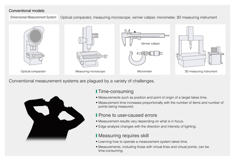
■ Conventional Dimensional Measurement
■ The New Standard
With the emergence of image dimension measurement systems, previously faced problems can be solved with just one measurement system.
■ Dimension Measurement System Benefits
Significant reductions in measurement time
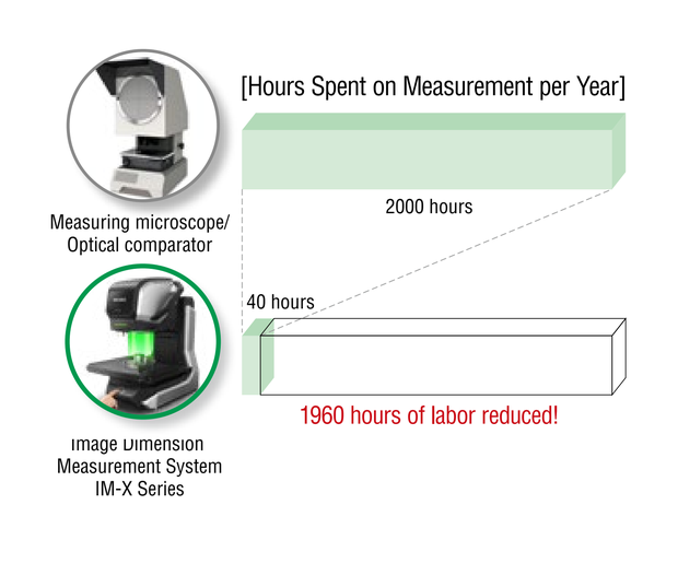
The steps required for measurement constitute simply placing the measurement target on the stage and pressing a button to begin measurement. These two steps are all it takes to obtain measurements for up to 5000 locations in just a few seconds. For example, let’s assume that conventional measurement methods require 10 minutes for one target. Conducting 50 measurements a day would amount to about 2000 hours per year. With the IM-X Series Image Dimension Measurement System, one measurement can be done in seconds, reducing the hours to just about 40 per year.
Elimination of user-caused measurement errors
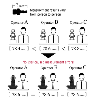
Conventional measurement systems require the user to decide the measurement point, where target edges should align, where the focus should be, and a host of other aspects that can lead to variations in measurement results depending on the habits and skills of the user. With an image dimension measurement system, positioning and orientation adjustment for a target are performed automatically, and measurement is performed for a set point. Manual operations that previously played a role in measurement errors, including measurement point specification, edge alignment, and focus adjustment, are no longer an issue.
Simple and convenient saving, searching, and statistical processing of measurement results
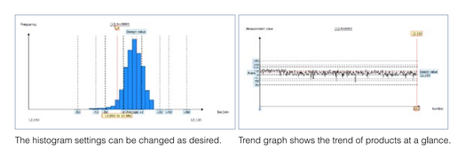
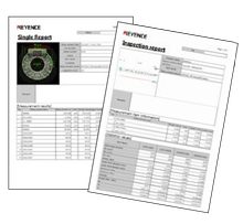
Inspection reports or analysis reports can be created easily.
All measurement results are automatically saved to the built-in hard disk drive. Critical statistical values required for inspection reports, including maximum/minimum values, averages, σ, 3σ, and CPK values, are calculated and displayed automatically just by selecting the measurement data. Inspection reports and analysis reports can also be created at the push of a single button.
More than just outline measurement from waveform images! 3 new functions
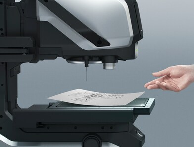
Import drawings and automatically create programs
Automatically retrieves the information needed for measurement from the drawing. The operator simply clicks the points to be measured on the screen. The measurement program automatically reflects information such as elements required for the measurement points, design values, tolerances, etc. There is no longer any need to spend time reading and interpreting drawings to create a program.
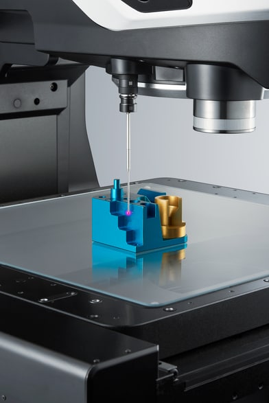
Accurate measurement in three dimensions
The low-measuring-pressure touch probe makes it easy to measure 3D machined shapes, including the perpendicularity of the top and side surfaces and the angle of slopes, which were difficult to detect with conventional measurement detects. It can also be used with commercially available styluses, allowing accurate measurement of deep holes and narrow grooves.
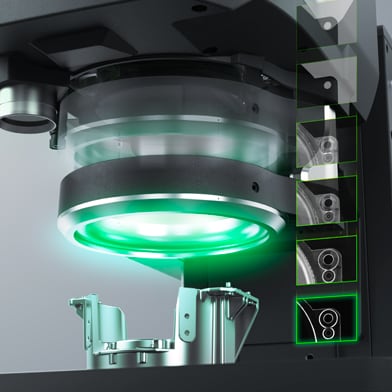
Automatically determine optimal focus and lighting with Smart Assist
Tasks such as focusing, illumination selection, and edge detection are now all automated. The measurement system itself can experiment with various conditions to find the optimal conditions for stability during continuous measurements. This allows anyone to reproduce measurements at an expert level.
Examples of Improvement
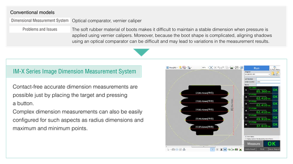
■ Boot
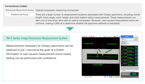
■ Charpy specimen
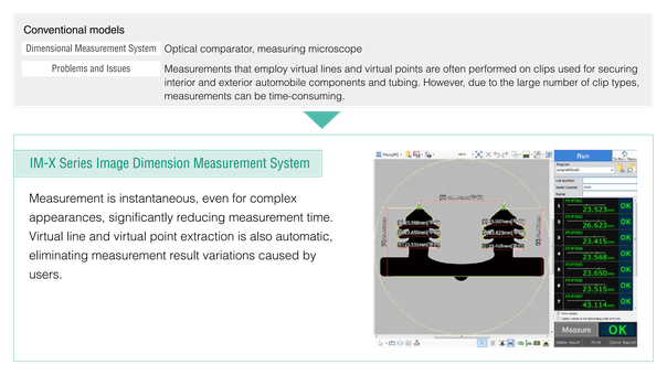
■ Clip
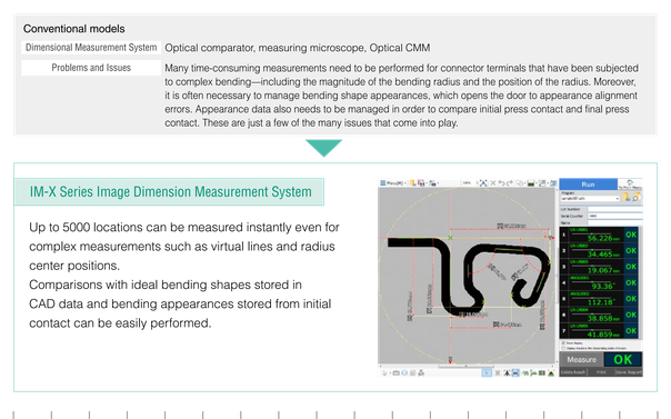
■ Connector terminal
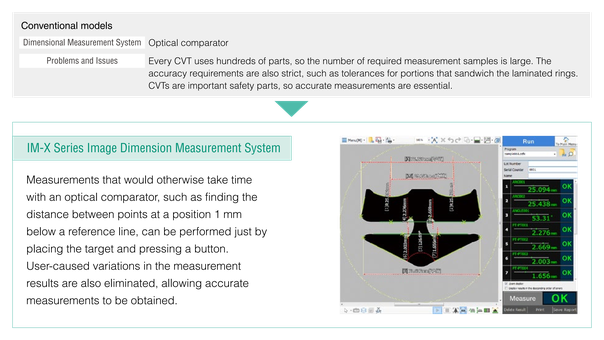
■ CVT element
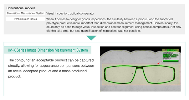
■ Designer goods (glasses)
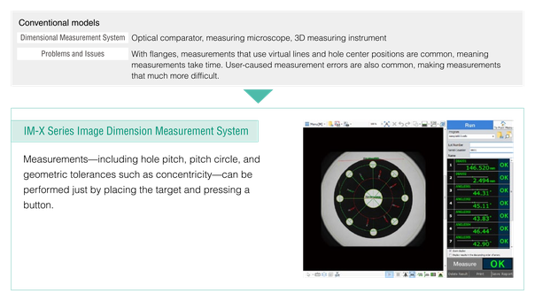
■ Flange
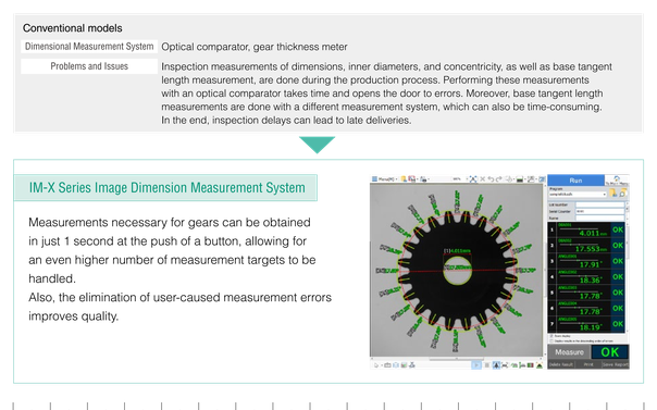
■ Gear
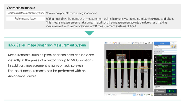
■ Heat sink
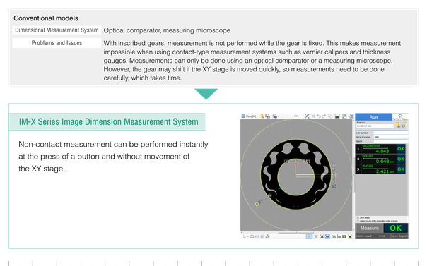
■ Inscribed gear
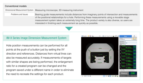
■ Linear guide
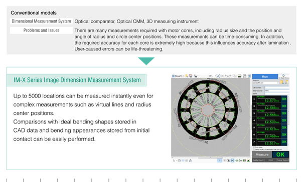
■ Motor core
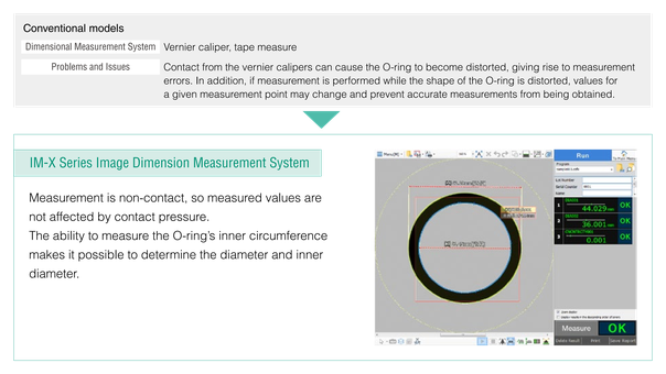
■ O-ring
■ Polygon mirror
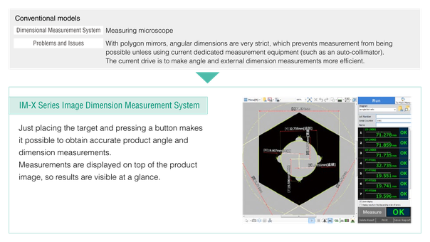
■ Rubber band
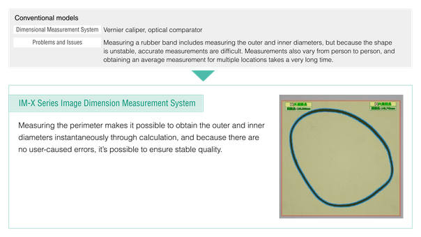
■ Screw
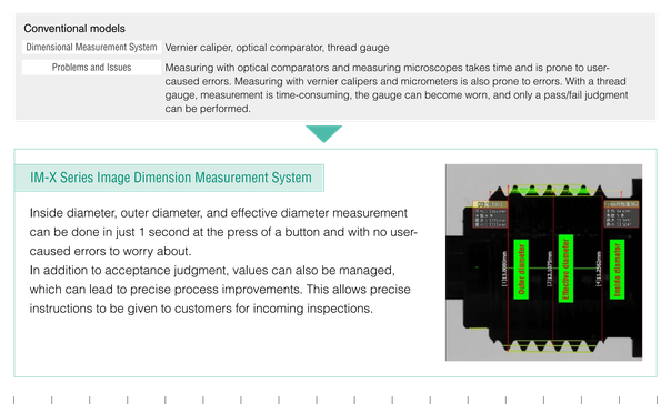
■ Spool valve
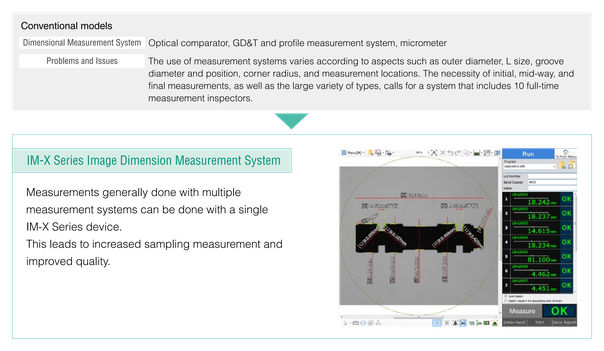
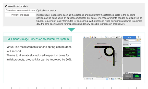
■ Torsion spring
■ Weatherstripping