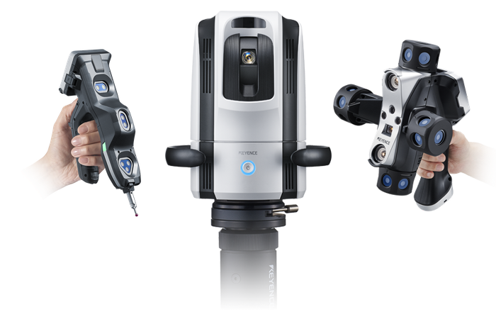
Easy to use for anyone, anywhere Portable and handheld 3D scanner and dimensional probing system
With a measurement range of up to 25 m (82.0'), single-person measurement is possible for various large targets. This wide range makes the WM valuable in diverse applications.
Conventional problems during measurement Measurement takes too long
Solutions with the WM Series
Overwhelming measurement speed
1 Measurement range
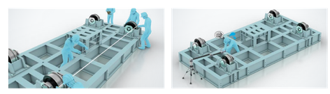
- ▪ Measurements of large products require two or three workers.
- ▪ It may not be possible to reach the desired measurement location.
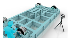
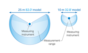
- ▪ The wide measurement range of the WM allows for single-worker measurement.
- ▪ The wide measurement range of the WM reduces the amount of blind spots.
2 Easy access to all functions
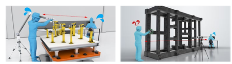
- ▪ A worker must write down the measurement results because they cannot be saved on the spot.
- ▪ During scanning, the number of points that have been acquired is unknown, so the worker must repeatedly move back-and-forth between the PC and the product.
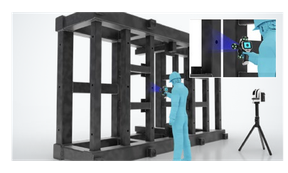
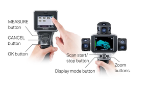
- ▪ The built-in touch screen of the WM makes it possible to check and save results on the spot.
- ▪ The scan can be checked on the spot.
3 Transporting the instrument to the site
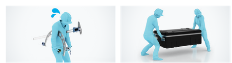
- ▪ It is necessary to transport various tools.
- ▪ The cases of conventional measuring instruments are large and hard to carry.
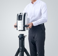
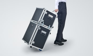
- ▪ Because the WM can handle various measurements, there is no need to transport various tools.
- ▪ Roughly the size of a suitcase, the dedicated case can easily be transported by a single person.
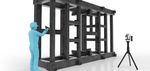
On-site measurement
Easily measure anything, anywhere in a wide variety of locations.
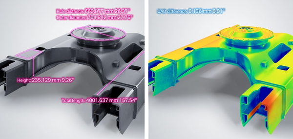
Dimensional and shape measurement
Choose from two probe types for measuring holes and other dimensional features as well as curved surfaces and complex shapes or comparing against CAD data.
Application Examples
1 Automobiles/EV/motorcycles
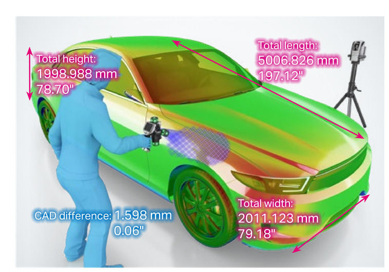
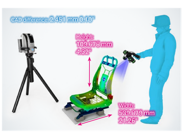
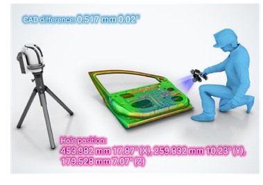
- ▪ Spot welding position confirmation
- ▪ Jig misalignment checking
- ▪ Specification inspection
- ▪ Overall seat shape measurement
- ▪ Door frame hole position measurement
- ▪ Giga casting overall shape checking
- ▪ Bumper shape measurement
- ▪ Battery case shape measurement
- ▪ Muffler bending angle checking
- ▪ Tire mold wear checking
- ▪ Pre-paint body overall shape checking
- ▪ Interference checking during chassis frame assembly
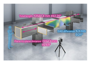
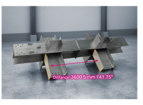
2 Steel frames/transmission towers
- ▪ Total length dimensional measurement
- ▪ Step height measurement
- ▪ Joint measurement
- ▪ Pillar vertical alignment accuracy measurement
- ▪ Cross-section dimensional and shape measurement
- ▪ Comparative measurement with 3D model
- ▪ Strain measurement
- ▪ Measurement of positions from pillar center
- ▪ Camber and base surface warpage measurement
- ▪ Gusset plate angle measurement
- ▪ Throat thickness measurement
- ▪ Pillar tilting measurement
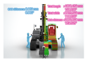
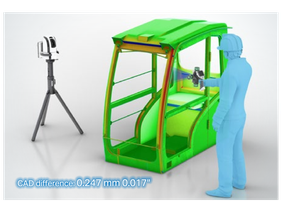
3 Construction equipment/agricultural equipment/forklifts
- ▪ Arm dimension checking
- ▪ Boom temporary weld dimensional measurement
- ▪ Cabin CAD comparative measurement
- ▪ Counterweight shape measurement
- ▪ Allocation from center circle of central frame
- ▪ Pipe bend angle measurement
- ▪ Bucket mounting hole position confirmation
- ▪ Oil tank assembly accuracy checking
- ▪ Engine case allowance checking
4 Concrete
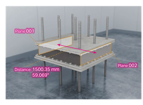
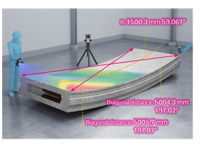
- ▪ Segment diagonal and arc measurement
- ▪ RC segment waviness and twisting measurement
- ▪ Box culvert strain checking
- ▪ Arch culvert dimensional measurement
- ▪ Comparative measurement of mold changes over time
- ▪ Concrete pile perpendicularity measurement
- ▪ Joint surface strain measurement
- ▪ Concrete slab and beam finished shape inspection
- ▪ Rubber bearing dimensional measurement
5 Pre-fabricated piping
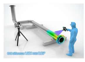
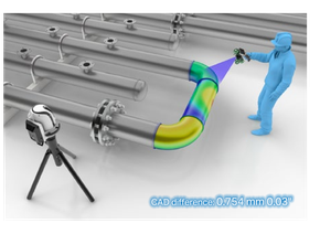
- ▪ Piping total length and partial length measurement
- ▪ Piping bent section and elbow angle measurement
- ▪ Flange tilting measurement
- ▪ Inter-flange positional relationship measurement
- ▪ Piping sketching/on-site inspection
- ▪ Pipe center axis measurement
- ▪ Entrance and exit position measurement
- ▪ Piping surface dent depth measurement
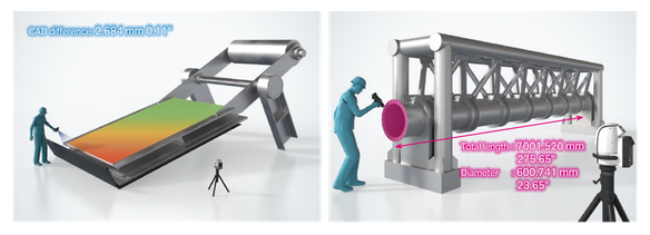
6 Floodgates/bridges/water pipe bridges
- ▪ Floodgate door flatness/perpendicularity measurement
- ▪ Bumper hole distance/R/height measurement
- ▪ Floodgate component distortion/deflection measurement
- ▪ Floodgate component crack length/width measurement
- ▪ Bridge material hole distance/diagonal dimensional measurement
- ▪ Bridge material scribing and marking support
- ▪ Bridge material on-site inspection/comparison before and after repairs
- ▪ Water pipe bridge material flange angle/tilt measurement
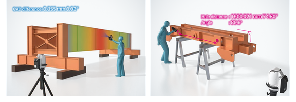
7 Hoist cranes
- ▪ Crane girder span and diagonal dimensional measurement
- ▪ Crane girder camber (warpage) measurement
- ▪ Wheel (trolley) parallelism/concentricity measurement
- ▪ Stand/saddle component dimensional/distortion measurement
- ▪ Crane component comparative inspection with CAD data
- ▪ Crane component on-site sketching and dimensioning
- ▪ Crane rail parallelism and linearity measurement
- ▪ On-site measurement during crane replacement/overhaul
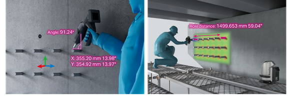
8 Bridge maintenance
- ▪ Anchor bolt position measurement/recording
- ▪ Crack length, width, and position measurement
- ▪ Bridge girder, bracket, etc. outer dimension and deformation measurement
- ▪ On-site sketching, finished shape measurement, and drawing
- ▪ Support section and girder vicinity on-site inspection
- ▪ Dimension comparison before and after repairs
- ▪ Displacement quantification
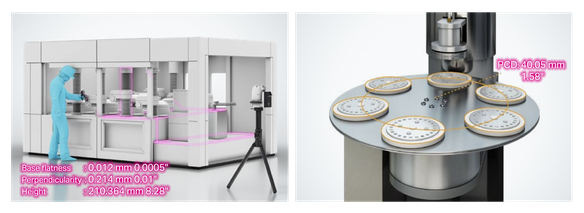
9 Semiconductor machines
- ▪ Machine frame diagonal dimension
- ▪ Stand strain measurement
- ▪ Roll-to-roll measurement
- ▪ Machine roll centering and parallelism measurement
- ▪ Leveling during the assembly process
- ▪ Installation accuracy checking
- ▪ Dimensional measurement of large components such as vacuum chambers and covers
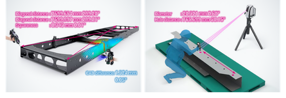
10 Machine tool covers/frames
- ▪ Cover outer dimension and hole position 100% inspection
- ▪ Cover flatness, perpendicularity, and warpage measurement
- ▪ Cover distortion and welding strain measurement (scan)
- ▪ Cover CAD data comparison
- ▪ Frame outer dimension, hole position, and distance measurement
- ▪ Frame flatness, perpendicularity, and parallelism measurement
- ▪ Frame distortion and welding strain measurement
- ▪ Frame incoming inspection and pre-shipping inspection optimization
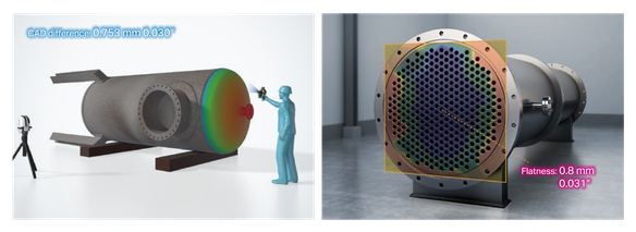
11 Heat exchangers/pressure vessels
- ▪ Flange center and installation angle measurement
- ▪ Heat exchanger total length and outer dimension measurement
- ▪ Sealing surface strain checking
- ▪ Post-assembly hole position and distance measurement
- ▪ Pressure vessel nozzle and opening positioning
- ▪ Pressure vessel head shape measurement
- ▪ Pressure vessel cap thickness measurement
- ▪ Flange height difference measurement
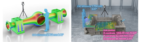
12 Large casting
- ▪ Casting allowance measurement/ 100% inspection
- ▪ Casting CAD data comparison
- ▪ Casting decentering/hole position measurement
- ▪ Casting distortion/warpage/deformation measurement
- ▪ Post-processing hole diameter/position/flatness measurement
- ▪ Casting on-site sketching
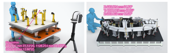
13 Welding jigs/transfer jigs/inspection jigs
- ▪ Welding jig assembly accuracy and positioning measurement
- ▪ Welding jig pin and holder position height and parallelism measurement
- ▪ Welding jig shim adjustment
- ▪ Transfer jig reference position measurement
- ▪ Transfer jig pin position measurement
- ▪ Quantitative management of wear and changes over time
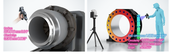
14 Rollers/chocks
- ▪ Roller outer diameter and inner diameter measurement
- ▪ Roller wear and change over time checking
- ▪ Roller total length, width, and inter-core distance measurement
- ▪ Roller installation position and centering
- ▪ Chock color map evaluation
- ▪ Shape comparison before and after overlaying
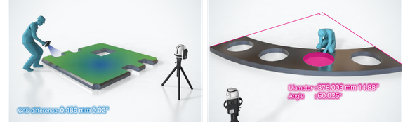
15 Thick plate fusion cutting
- ▪ Hole position measurement after thick plate fusion cutting
- ▪ Fusion-cut part strain and deformation inspection
- ▪ Cutting width measurement after fusion cutting
- ▪ Fusion-cut part angle measurement
- ▪ Fusion cutting line straightness measurement
- ▪ Fusion-cut part weld bead shape measurement
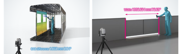
16 Railroads
- ▪ Car frame dimensional measurement
- ▪ Cart strain and warpage measurement
- ▪ Door hole position measurement
- ▪ Under-the-floor power distribution box perpendicularity measurement
- ▪ Wheel, axle, pantograph, etc. wear checking
- ▪ Platform door dimensional measurement
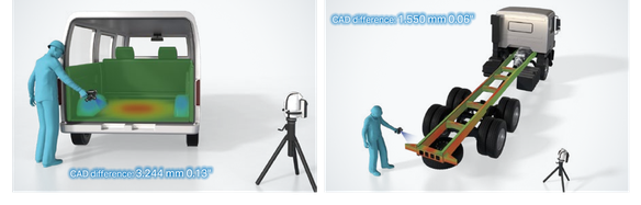
17 Special vehicles
- ▪ Vehicle frame dimensional measurement
- ▪ Chassis diagonal dimensions
- ▪ Sub frame distance measurement
- ▪ Customized component perpendicularity measurement
- ▪ Cabin CAD comparison
- ▪ Vehicle overall pre-shipping inspection
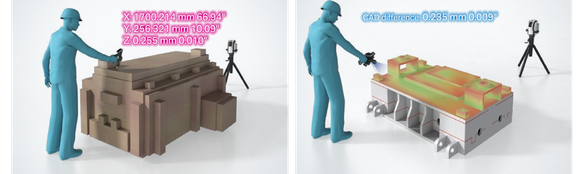
18 Wooden molds/styrofoam molds
- ▪ Wooden mold CAD data comparative measurement
- ▪ Wooden mold wear and change over time checking
- ▪ Pre- and post-repair quantitative management
- ▪ Styrofoam mold tapered part measurement
- ▪ Styrofoam mold curved surface shape inspection
- ▪ Styrofoam mold cross-section shape measurement
- ▪ Styrofoam mold welding, welded part dimension inspection
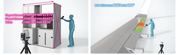
19 Aerospace
- ▪ Aircraft wing curved surface shape measurement
- ▪ Aircraft frame hole position confirmation
- ▪ Aircraft door installation surface inspection
- ▪ Galley dimensional measurement
- ▪ Aircraft component CAD comparative measurement
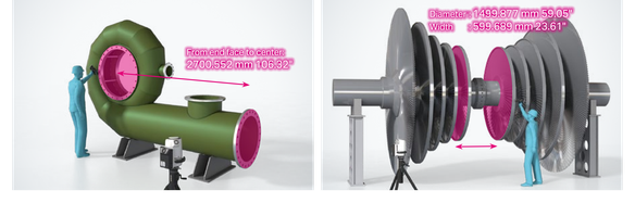
20 Power generation
- ▪ Turbine dimensional measurement
- ▪ Pump shape comparison
- ▪ Water turbine component wear amount checking
- ▪ Boiler component strain measurement
- ▪ Overhaul sketching
- ▪ Power generator cover overall dimensional measurement
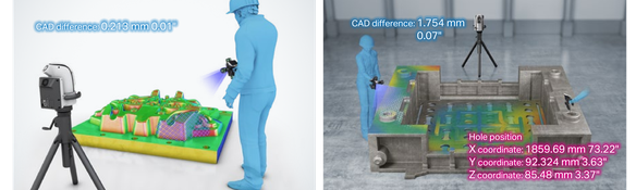
21 Mold maintenance
- ▪ Quantitative management of mold wear and changes over time
- ▪ Mold CAD data comparative inspection
- ▪ Immediate measurement in the event of on-site defects or repairs
- ▪ Mold pin position measurement
- ▪ Groove width/depth measurement
- ▪ Mold flatness measurement
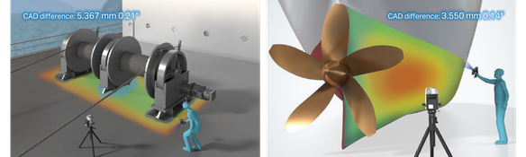
22 Shipbuilding
- ▪ Large propeller shape and dimensional measurement
- ▪ Hull block dimensional measurement
- ▪ Large tank and door dimension inspection
- ▪ Piping bending angle
- ▪ CAD comparison for valves and other components with complicated shapes
- ▪ Mast base flange flatness
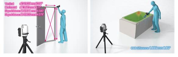
23 Household equipment
- ▪ Dimensional measurement of pressed metal products for kitchens and bathrooms
- ▪ Sink component fitted part cross sectional shape measurement
- ▪ Bathroom and washbasin head shape measurement
- ▪ Toilet seat and plastic tray shape measurement
- ▪ Wooden mold and rubber mold free-form shape cross section measurement
- ▪ Chair frame measurement