Measurement case studies of the WM Series, a Wide Area CMM Deformation Processing
Dimensional and shape measurement of large workpieces
Concept of the WM Series
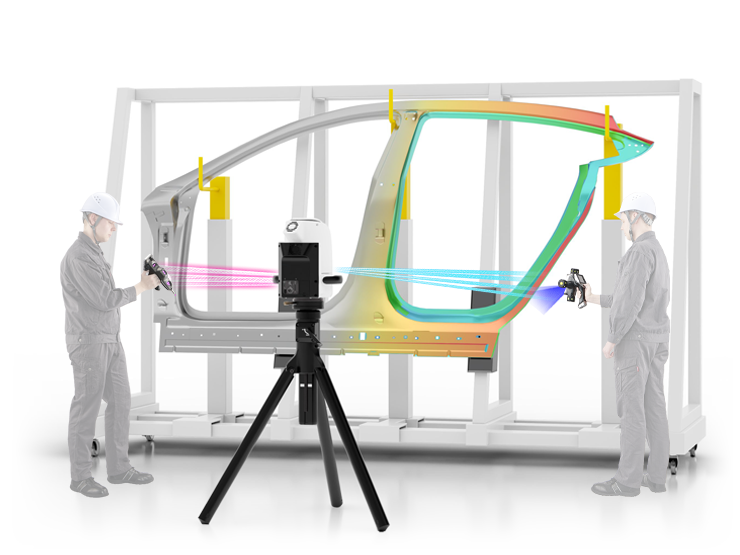
The WM Series allows for all types of measurement, from dimensions to GD&T and even 3D form/shape, right on the shop floor. It solves the challenges of conventional measurement processes by creating "Simple measurement, for everyone, everywhere".
Three key features of the WM Series
POINT1
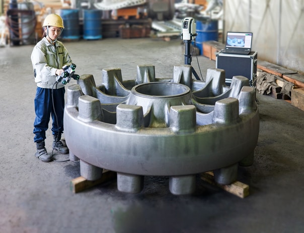
Single-person operation is possible with a handheld probe and a maximum measurement range of 25 m 82.0', enabling measurement of various large objects.
POINT2
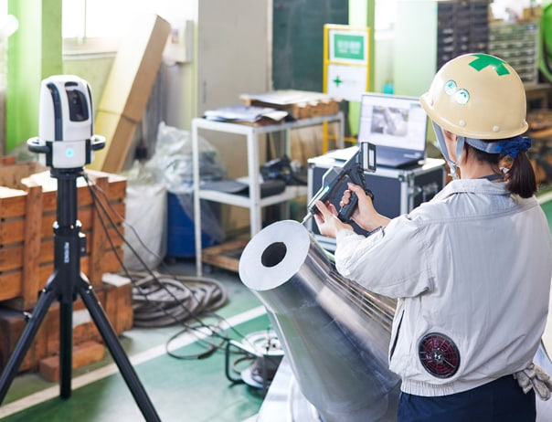
On-site measurement can easily be performed anywhere for the products you want, even in diverse environments.
POINT3
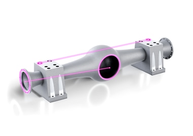
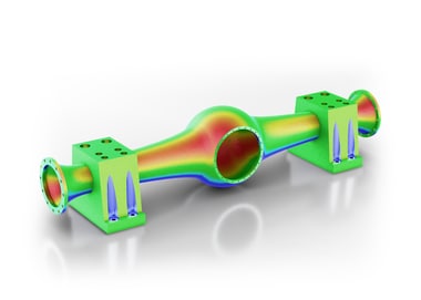
Dimensions and shapes can be measured using two types of probes — from hole positions to complex curved surfaces and CAD comparison.
Case study Pressing, Casting, Forging, Resin Molding, and More
Pressed Parts
Overall Shape Comparison of Good Parts and NG Parts
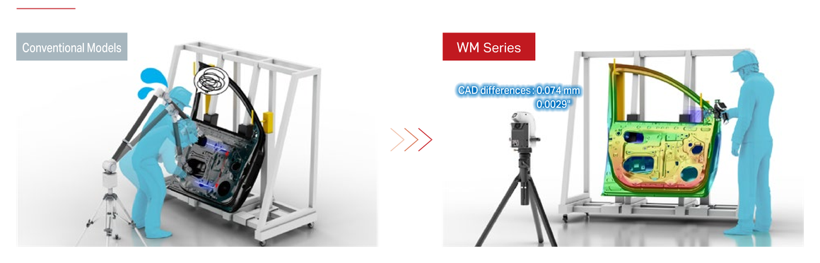
Quantifying surface inspection results, curvature, and warpage is time-consuming. Differences are also difficult to identify through visual inspection. Large parts, in particular, are difficult to measure, leading to lengthy inspections and heavy workloads on the shop floor.
The overall shape of a product can be visualized in color. Even for large parts, you can quickly identify whether they are in or out of spec.
Bending Radius / Springback / Bending Angle
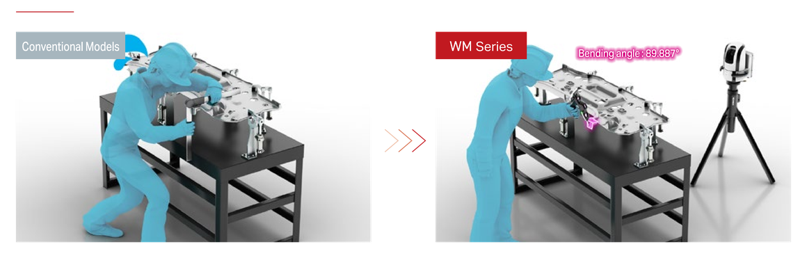
Springback and bending angle measurements are prone to variations between operators. Quantifying the bending radius is also difficult.
You can measure springback and bending angles without variations between operators. You can analyze the bending radius and angle in cross-sections, and track trends over time.
Casting and Forging Parts
Thermal Deformation After Molding
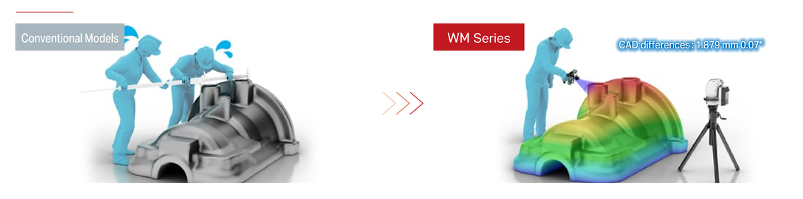
Managing thermal deformation after molding is difficult, and confirming distortion before and after machining is time-consuming.
You can manage thermal deformation after molding, which enables instant determination of the correction amount required during machining.
Confirming Machining Allowances
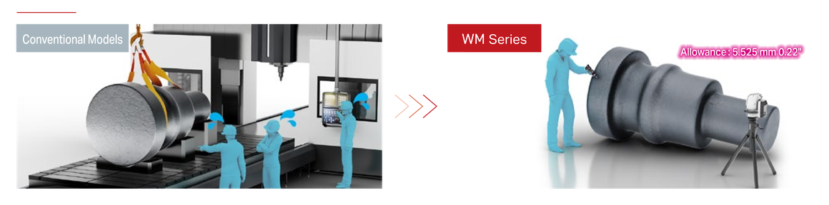
Confirming machining allowances is time-consuming and affects the machining yield rate. Inaccurate confirmation of machining allowances also leads to material loss.
You can quickly confirm machining allowances, which improves the machining yield rate. Improved confirmation accuracy also reduces material loss.
Resin-Molded Parts
Hole Position (XYZ Coordinates) / Hole Distance
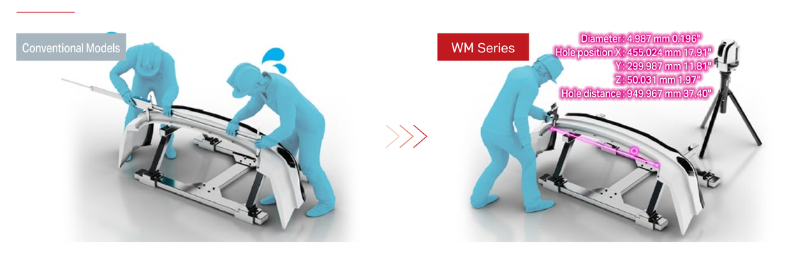
When measuring small holes in thin or soft materials with hand tools, variations occur between operators.
The contact probe enables high-accuracy measurement of small diameters. It also allows you to manage hole taper and hole position.
Corner Radius / Draft Taper
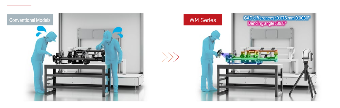
Measuring draft taper and corner radius is difficult due to variations caused by mold temperature and wall thickness.
You can measure warpage, draft taper, and corner radius, providing valuable data for improving mold design and cooling settings.
Mold (Inspection and Management)
You can perform product measurement and mold management on-site with a single measurement system.
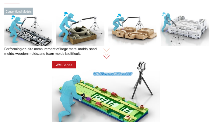
Overall Mold Shape Comparison
By bringing the WM Series to the site, anyone can easily perform shape comparisons of large parts.
Mold Surface Wear Management
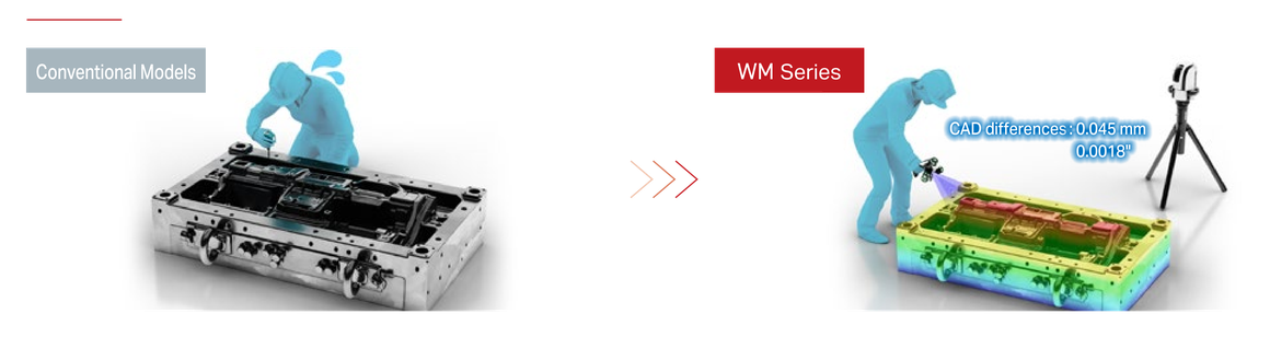
Mold surface wear management is prone to variations between operators.
You can manage mold surface wear consistently without variations. As the color map shows you any deviations from previous data, worn areas can be identified instantly.
Upper and Lower Mold Matching Simulation
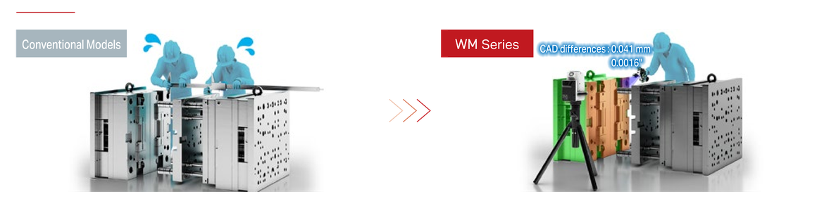
Transportation and setup are time-consuming, making the mold matching work complex.
By scanning the upper and lower molds, you can simulate mold matching. This reduces the time required for transportation and setup.
The Ideal Measurement System for Deformation-Processed Parts
This measurement system is highly acclaimed by customers who manufacture deformation-processed parts (pressing, casting, forging, and resin molding).
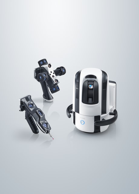
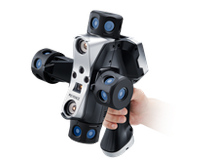
Rapid Measurement of Deformation-Processed Parts Scanning Probe
The WM Series is equipped with an industry-first violet laser, enabling measurement on all surfaces, even those that are black or reflective, without the need for using spray.
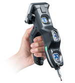
High-Accuracy Mold Management and Measurement Contact Probe
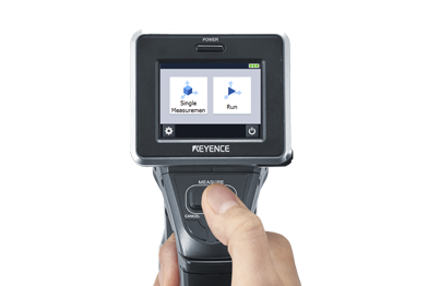
The wireless probe allows measurement from any angle, making it easy for anyone to use.
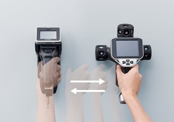
Switching Probes Is as Simple as Swapping Your Grip
Simply switch between contact measurement and scanning by swapping the probe. This makes the system easy for anyone to use.
Ready to Measure in Just 2 Minutes Easy Setup
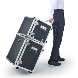
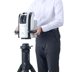
Simply carry the system to your measurement location and place the camera on the tripod to start measurement.