Dimensional and shape measurement of large workpieces Manufacturing and Sheet Metal Processing
Measurement case studies of the WM Series, a Wide Area CMM
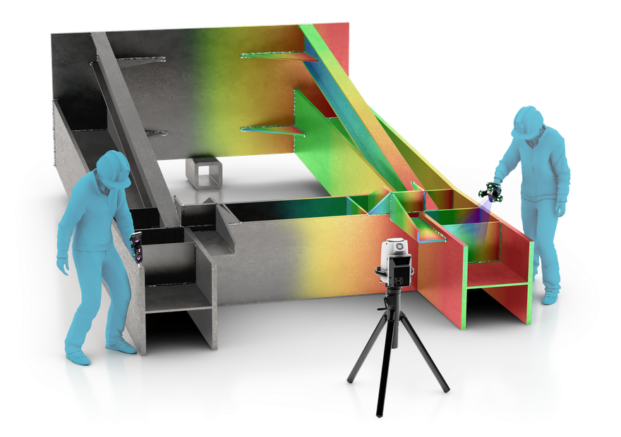
- Total length: 3999.98 mm 157.48”
- Width: 3700.15 mm 145.68”
- CAD differences: 0.52 mm 0.0205”
Concept Concept of the WM Series
The WM Series addresses the challenges of conventional analog measurement and manual work. “Simple measurement is available for everyone, everywhere—easy, accurate, and digital.”
Three key features of the Series
POINT 1
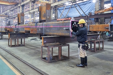
Single-person operation is possible with a handheld probe and a maximum measurement range of 25 m 82.0’, enabling measurement of various large objects.
POINT 2
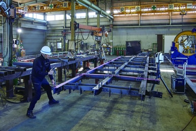
On-site measurement can be simply performed anywhere for the products you want, even in diverse environments.
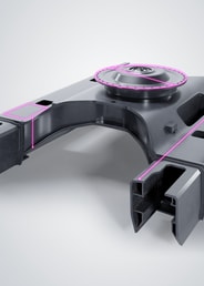
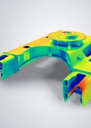
POINT 3
Dimensions and shapes can be measured using two types of probes—from hole positions to complex curved surfaces and CAD comparison.
- Outer diameter: 704.842 mm 27.75”
- Hole pitch: 669.877 mm 26.37”
- Height: 235.129 mm 9.26”
- Total length: 4001.637 mm 157.54”
- CAD differences: 0.136 mm 0.01”
Measurement case studies WM solves all conventional challenges alone
CASE 01 Outer dimensions (length, width, and height)
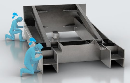
Conventional methods
Large workpieces require two or more people, causing variations in measured values
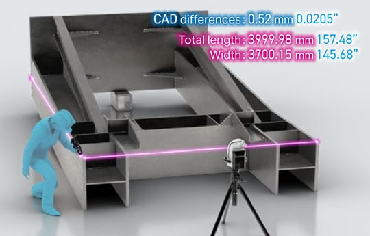
WM Series
Large workpieces can be measured easily and accurately by a single person
CASE 02 Diagonal dimensions and differences
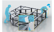
Conventional methods
Diagonal measurements require 2 people and are difficult to perform when obstructed
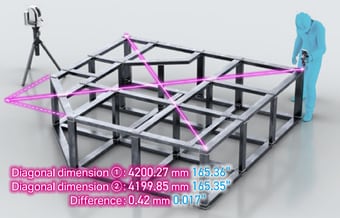
WM Series
Even a single person can perform instant diagonal measurements with automated difference calculation
CASE 03 Inner diameter, outer diameter, and hole pitch

Conventional methods
Measuring large-diameter or recessed holes is challenging
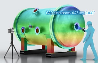
WM Series
Holes of any size or position can be easily measured
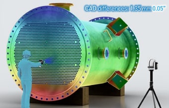
CASE 04 Post-welding strain
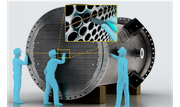
Conventional methods
Visual checks using mason’s line or scale are difficult to quantify
WM Series
Clear identification of correction points is possible, reducing rework time
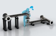
CASE 05 Post-welding deformation
Conventional methods
Checking with a try square is time-consuming and raises concerns about accuracy
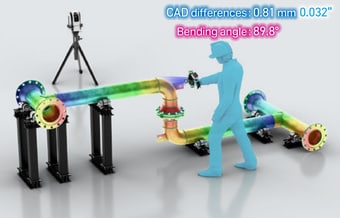
WM Series
Instant numerical measurement of angle and tilt is possible
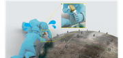
CASE 06 Marking
Conventional methods
Establishing reference points is difficult and relies on the operator's experience
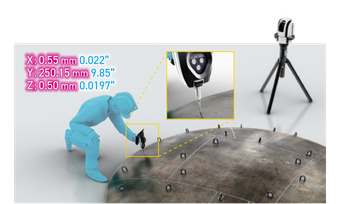
WM Series
Anyone can mark in the same position, enabling standardized work
CASE 07 Level adjustment
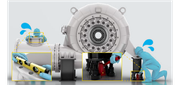
Conventional methods
Leveling with spirit levels or plumb bobs takes time
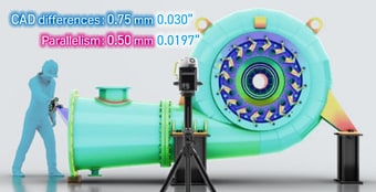
WM Series
Workload for leveling tasks and post-installation adjustments is reduced
CASE 08 Allowance confirmation
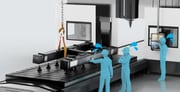
Conventional methods
Comparing dimensions before and after machining is labor-intensive, often resulting in defects from leaving or removing too much material
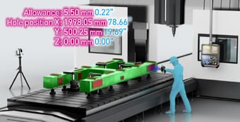
WM Series
Differences between dimensions before and after machining are automatically calculated, visualising excess or insufficient material allowance
CASE 09 Measurement at the tack welding stage

Conventional methods
Defects discovered after final welding lead to rework and backtracking
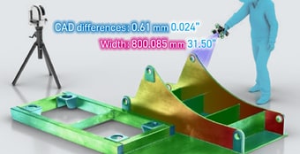
WM Series
On-site measurement during tack welding enables instant evaluation and immediate correction, eliminating the need for rework
CASE 10 Missed weld and missed hole

Conventional methods
Visual and manual checks introduce oversight risks
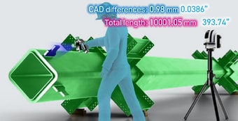
WM Series
Color mapping instantly visualizes any missed markings
CASE 11 Weld bead height and width
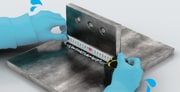
Conventional methods
Measurement with gauges or calipers is labor-intensive and inaccurate
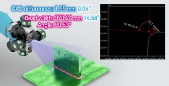
WM Series
Cross-sectional profiles can also be digitized, making documentation and verification straightforward
CASE 12 CAD comparison

Conventional methods
Verifying differences between CAD data and the physical object is challenging
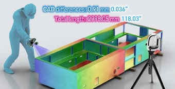
WM Series
Easy comparison between 3D CAD data and the physical object is provided along with automatic OK/NG judgment
CASE 13 Inspection report
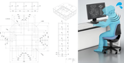
Conventional methods
Manual entry and Excel transcription are time-consuming and prone to writing and typing errors
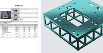
WM Series
Measurement data is automatically saved and transferred, eliminating transcription errors
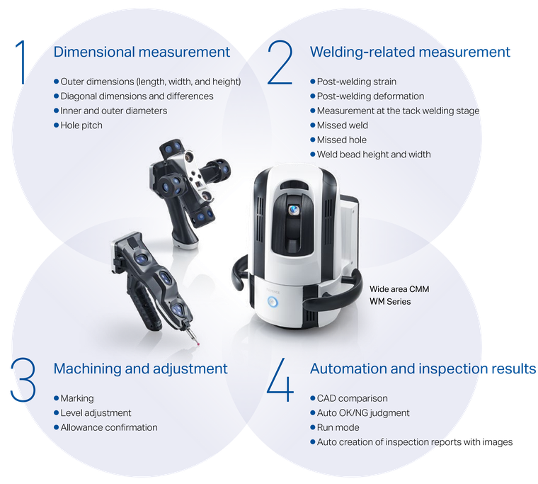
WM application processes
The WM Series delivers results at every stage—from workforce reduction and workload savings to enhanced quality assurance, digitalization, and client support
Support for all display digit counts
The number of display digits can be adjusted to suit the requirements of in-process confirmation during manufacturing, final tuning within the facility, or the precision standards specified by clients.
- 1 mm 0.0394” increments
- 0.1 mm 0.0039” increments
- 0.01 mm 0.0004” increments