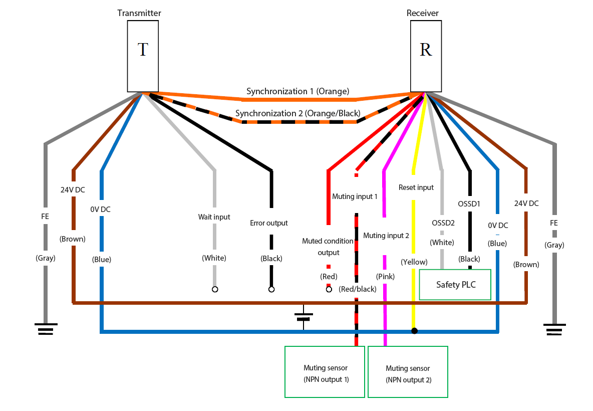
NPN Wiring System: Wire Synchronization System (Transmitter: 7-Core Cable, Receiver: 11-Core Cable)
Settings must be configured via software.
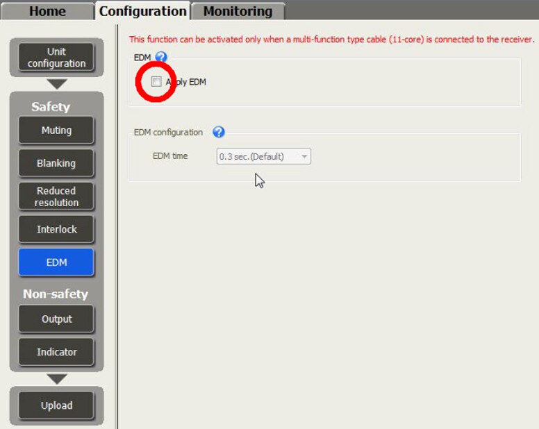
| EDM |
Not used |
| Start/Restart interlock |
Automatic |
| Muting |
Used |
| Transmitter cable |
7 cores |
Example) GL-RP5NS |
| Receiver cable |
11 cores |
Example) GL-RP5NM |
- Independently insulate any unused wires. Do not bundle them together.
- A safety device such as a safety controller can be used in place of the safety PLC.
- Connect 0 V on the safety PLC to 0 V on the GL-R.
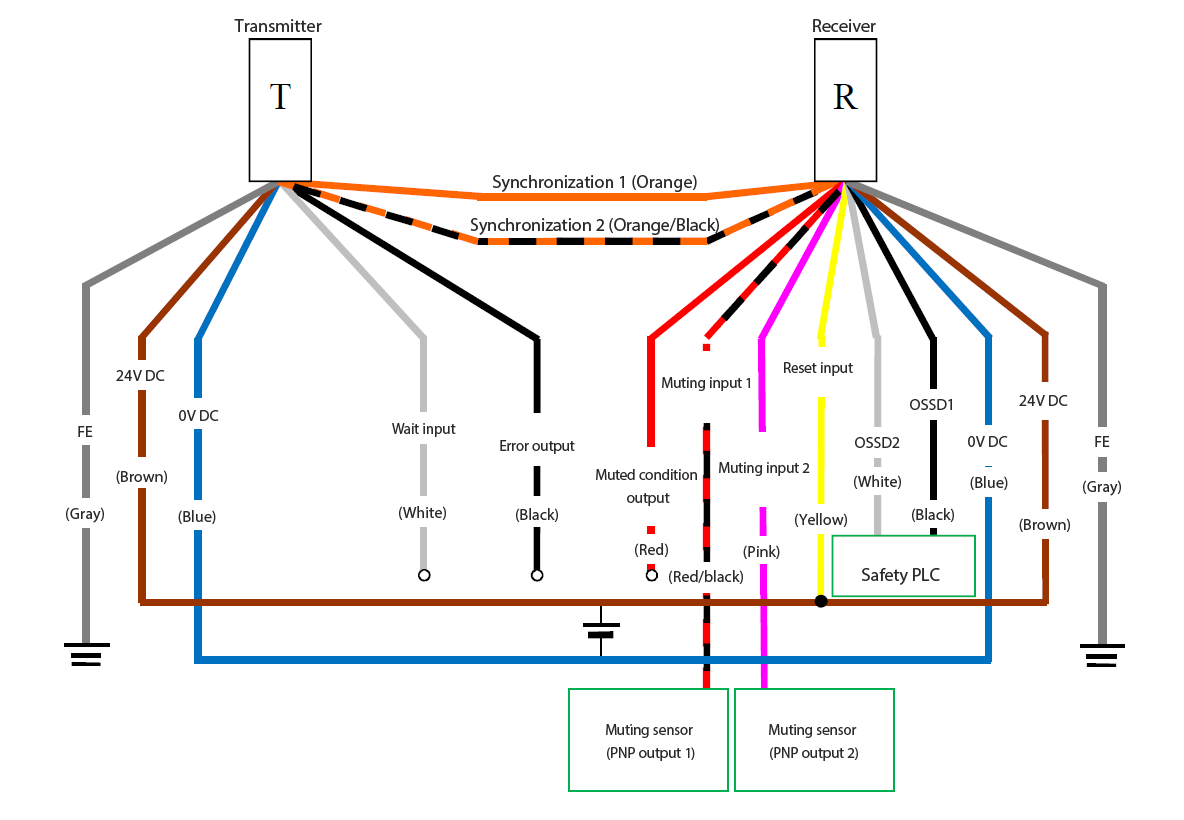
PNP Wiring System: Wire Synchronization System (Transmitter: 7-Core Cable, Receiver: 11-Core Cable)
Settings must be configured via software.
| EDM |
Not used |
| Start/Restart interlock |
Automatic |
| Muting |
Used |
| Transmitter cable |
7 cores |
Example) GL-RP5PS |
| Receiver cable |
11 cores |
Example) GL-RP5PM |
- Independently insulate any unused wires. Do not bundle them together.
- A safety device such as a safety controller can be used in place of the safety PLC.
- Connect 0 V on the safety PLC to 0 V on the GL-R.
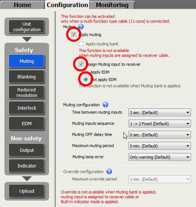
Settings must be configured via software.
| EDM |
Not used |
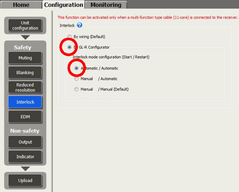
| Start/Restart interlock |
Automatic |
| Muting |
Used |
Muting
Start/Restart Interlock
EDM