
GL-R Wiring Example 24
| EDM | Used |
|---|---|
| Start/Restart interlock | Manual |
| Transmitter cable | 7 cores | Example) GL-RP5NS |
|---|---|---|
| Receiver cable | 11 cores | Example) GL-RP5NM |
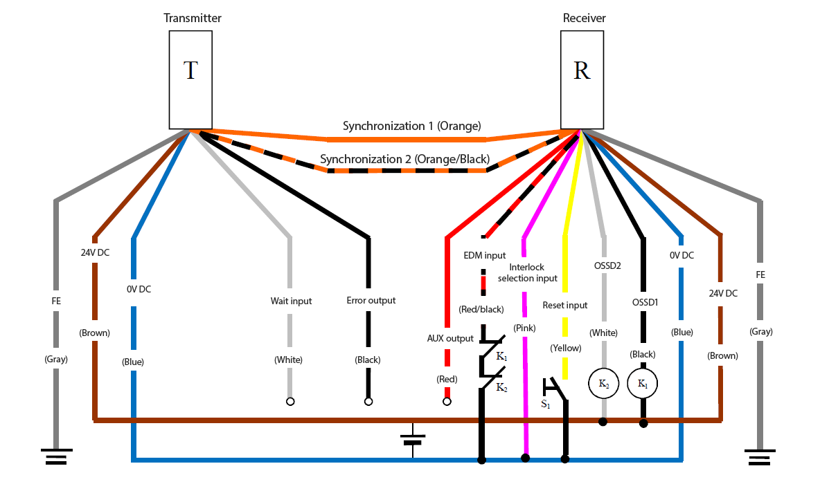
- Independently insulate any unused wires. Do not bundle them together.
NPN Wiring System: Wire Synchronization System (Transmitter: 11-Core Cable, Receiver: 11-Core Cable)
| EDM | Used |
|---|---|
| Start/Restart interlock | Manual |
| Transmitter cable | 11 cores | Example) GL-RP5NM |
|---|---|---|
| Receiver cable | 11 cores | Example) GL-RP5NM |
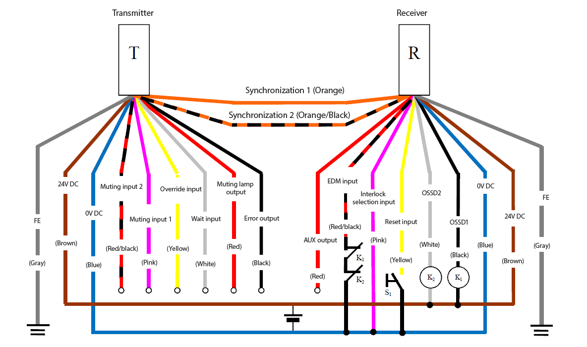
- Independently insulate any unused wires. Do not bundle them together.
| EDM | Used |
|---|---|
| Start/Restart interlock | Manual |
| Transmitter cable | 7 cores | Example) GL-RP5PS |
|---|---|---|
| Receiver cable | 11 cores | Example) GL-RP5PM |
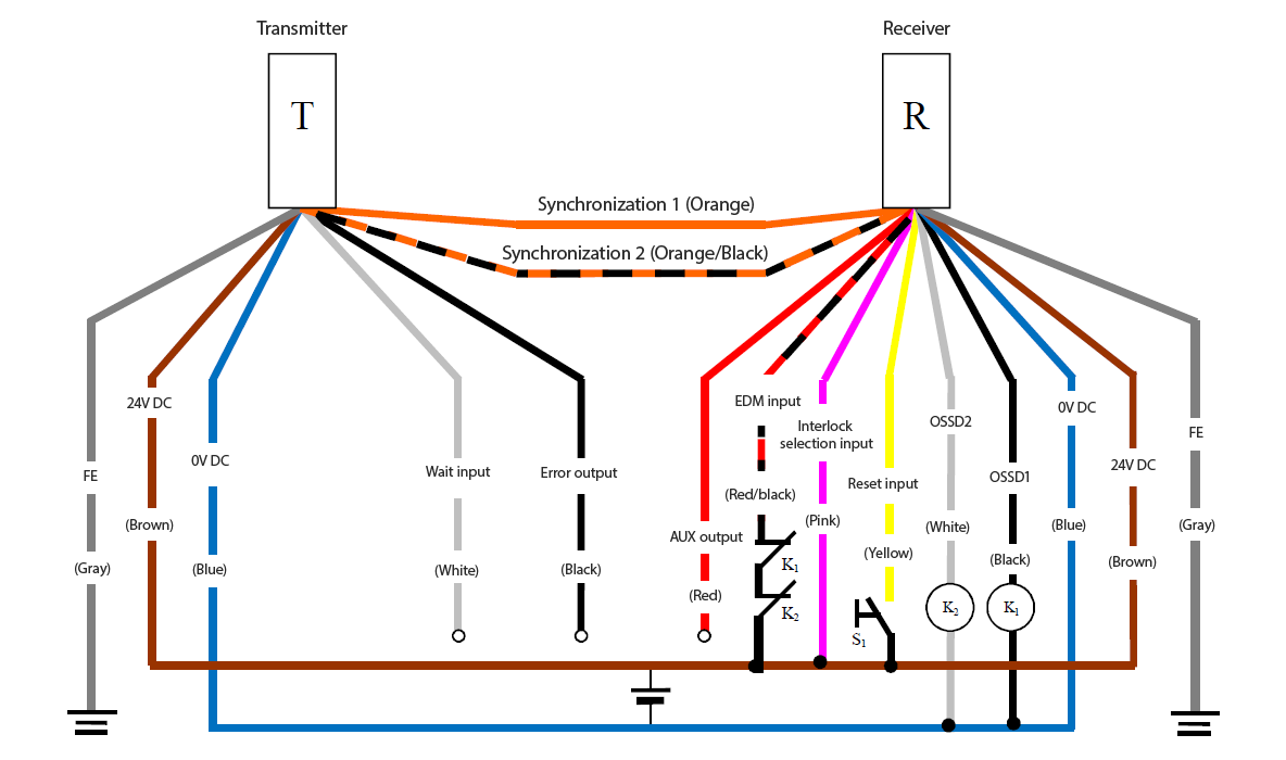
- Independently insulate any unused wires. Do not bundle them together.
PNP Wiring System: Wire Synchronization System (Transmitter: 11-Core Cable, Receiver: 11-Core Cable)
| EDM | Used |
|---|---|
| Start/Restart interlock | Manual |
| Transmitter cable | 11 cores | Example) GL-RP5PM |
|---|---|---|
| Receiver cable | 11 cores | Example) GL-RP5PM |
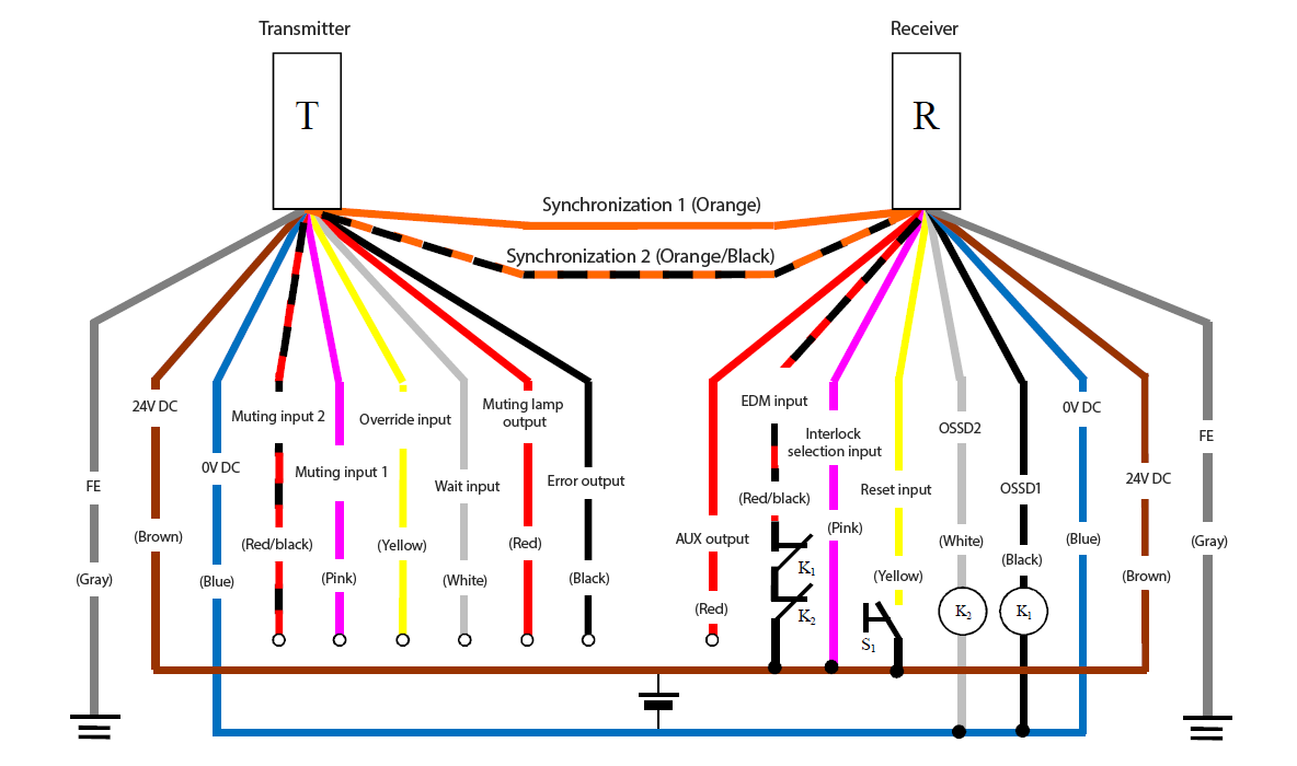
- Independently insulate any unused wires. Do not bundle them together.
