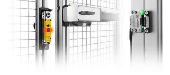
Main Unit Model: GS-73PC
PNP
| OSSD operation | Lock link mode |
|---|---|
| Interlock function | Automatic |
| EDM function | Used |
| Applicable model | Main unit | Cable |
|---|---|---|
| Locking type | GS-73PC | GS-P12C5, 10, 20 No extension cable |
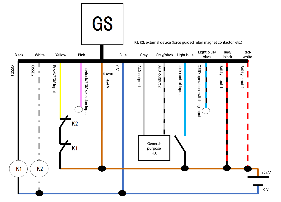
| Required | Pin | Color | Icon above | Function |
|---|---|---|---|---|
| 1 | Brown |  |
+24 V | |
| 3 | Blue |  |
0 V | |
| 4 | Black |  |
OSSD1 | |
| 7 | White |  |
OSSD2 | |
| 2 | Red/black |  |
Safety input 1 | |
| 6 | Red/white |  |
Safety input 2 | |
| 5 | Gray |  |
AUX output 1 | |
| 9 | Gray/black |  |
AUX output 2 | |
| 10 | Light blue |  |
Lock control input | |
| Open | 12 | Light blue/black |  |
OSSD operation switching input |
| 11 | Yellow |  |
Reset/EDM input | |
| Open | 8 | Pink |  |
Interlock/EDM selection input |
- The required wiring ensures that operations can be checked without errors.
- Independently insulate any unused wires. Do not bundle them together.
