Non-contact surface roughness/profile measuring Instruments
A non-contact measuring instrument uses light in place of the stylus of used in a contact-type measuring instrument. These instruments come in multiple types, such as confocal and white light interference, and vary depending on the principle used. There are also a variety of contact-type detectors that have been changed into non-contact instruments by replacing the probe with optical sensors and microscopes. We will use KEYENCE's 3D laser scanning microscope, the VK-X Series, as an example to explain the principles of confocals.
A 3D laser scanning microscope uses the confocal principle, and a laser as the light source, to measure the asperity of the target's surface.
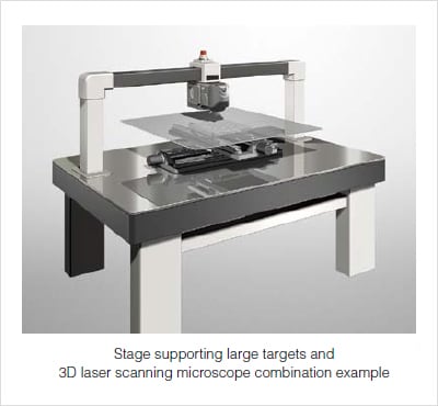
The system is configured as shown in the figure on the right. Set the sample on the XY stage of the measurement unit and perform the 3D scan.
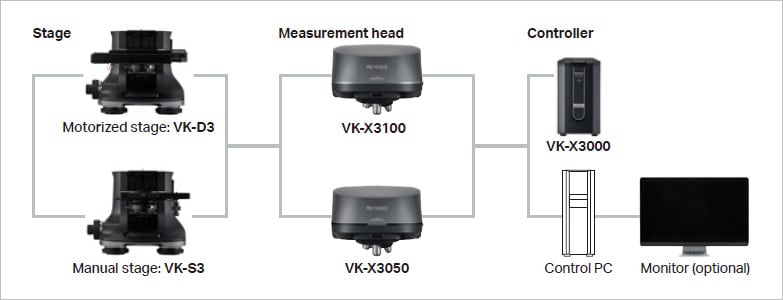
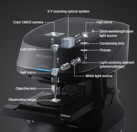
With KEYENCE's VK-X Series, an X-Y scanner is embedded in the measurement unit. The laser light source scans across the surface of the target in the X and Y directions and acquires the surface data.
The scanning principles are explained below.
3D laser scanning microscope measurement principles
- 1. The laser beam emitted from the laser light source scans the target surface.
- 2. The laser light is reflected from the target surface, passes through the half mirror, and enters the light-receiving element. At this point, the laser intensity of the received reflection, as well as the height position of the lens, are recorded by the microscope. The laser microscope acquires 1024 data points in the X direction and 768 data points in the Y direction, and records the intensity and lens height for each point (1024 x 768 = 786432 points).
- 3. When the scan of one surface finishes, the objective lens moves in the Z direction by the specified pitch.
- 4. The same surface scan is performed again for the surface that the objective lens has moved to, and the laser’s reflected light intensity is checked over 1024 × 768 points. The reflected light intensity of each pixel is compared with the reflected light intensity recorded in memory as “v”. If the new reflected light intensity is higher, the reflected light intensity data and lens height position data are overwritten.
- 5. The operations of steps (2) to (4) are repeated for the specified Z distance.
- 6. Finally, for each of the 1024 × 768 pixels, the reflected light intensity and lens height position are recorded in memory at the time when the strongest laser light reflection was received.
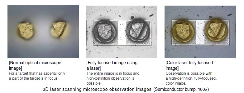
- 7. For optical microscopes, the WD (Working Distance: the distance from the objective lens to the target) when the objective lens is in focus is constant. If it is assumed that the image is in focus when the reflected light intensity is at maximum, it is possible to obtain 3D data in the observation area (1024 × 768 pixels) of the microscope by stitching together the lens height positions from the different times that the image was in focus, that is, when the reflected light intensity was at its maximum.
3D laser scanning microscope accuracy
The ability to accurately read the peak value of the reflected light intensity has a large effect on the measurement accuracy of laser confocal measurement systems.
There are many ways to construct a confocal optical system. The pinhole confocal method used in KEYENCE's 3D laser scanning microscope is explained below:
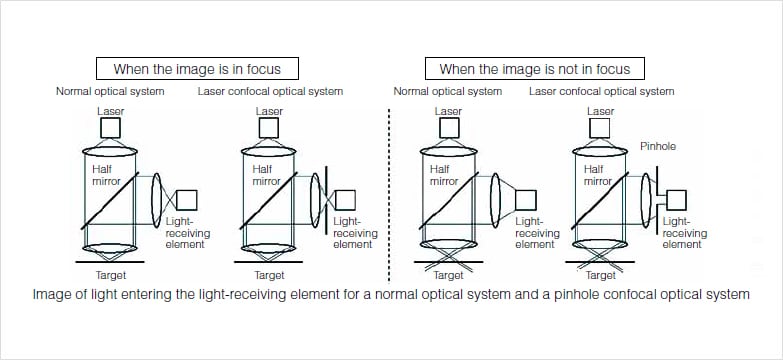
With the pinhole confocal method, a pinhole is placed in front of the light-receiving element. The pinhole has a diameter of just tens of micrometers and has the role of blocking reflected light when the image is not in focus.
When the image is in focus (see figure below), the reflected light is received by the light-receiving element in both the normal optical system and the laser confocal optical system. When the image is not in focus, the reflected light (out-of-focus light) enters the light-receiving element for normal optical systems, but is blocked by the pinhole when using the pinhole confocal method. In other words, the structure is such that the reflected light only enters the light-receiving element when the image is in focus.
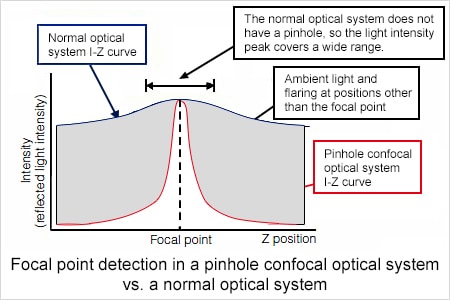
The pinhole's effect on the received light is illustrated in the figure on the right. With the laser confocal, the reflected light intesntiy peaks at the focal point. On the other hand, the normal optical system results in a gently sloping curve.
The lack of a peak at the focal point makes it difficult to detect when the target is in focus.
Laser XY-direction resolution
For non-contact systems, the light beam spot corresponds to the stylus of contact-systems. Non-contact systems do not directly touch the target, therefore they do not have the disadvantages of stylus wear and the risk of scratching a sample. The size of the beam spot diameter is important in order to accurately measure the profile of a sample. Generally, the smaller the beam spot diameter, the smaller the features that can be measured.
Laser microscopes use lasers for their light sources, which makes it possible to create an extremely small beam spot.
When using a 150x (N.A. = 0.95) objective lens, the VK-X Series, which uses a 404 nm violet laser for its laser light source, achieves a resolution of 0.13 μm 0.005 Mil for the planar spatial resolution. A laser microscope can measure asperity with a very small width, which cannot be measured with contact-type systems.