Measurement/inspection of weld surface
In addition to visual inspection, there are several methods of weld surface inspection such as magnetic particle testing (MT), penetrant testing (PT), and inspection using a vision system or a laser displacement sensor.
This page introduces welding surface measurements and inspections.

- Contact-type surface inspection
- Conventional non-contact-type surface inspection
- Non-contact-type surface inspection with a laser displacement sensor
Contact-type surface inspection
- Magnetic particle testing (MT)
- This method is suitable for detection of flaws on and near the surface of strongly magnetic materials such as iron and steel. When a weld workpiece is magnetized, a discontinuity occurs in the magnetized area where a flaw exists on the surface or in the shallow subsurface (within approx. 2 to 3 mm of the surface). The magnetic flux leaks from the part and causes magnetic poles along the border of the discontinuity. When magnetic particles are applied to the surface of the weld in this state, they turn into tiny magnets and are attracted to the magnetic poles around the flaw. The particles form a magnetic particle pattern showing a line several to several ten times thicker than the width of the actual flaw, which allows visual observation of the flaw.
- Penetrant testing (PT)
- This method can be used for the surface inspection of almost all materials. Highly penetrative liquid of visible colors or gloss (penetrant) is applied to the surface of a weld. After the liquid penetrates into flaws, a developer is applied to draw the liquid out and enlarge the flaw, which allows visual observation.

Conventional non-contact-type surface inspection
The surface inspection was done visually by experienced welding workers. Such visual inspection has various problems, including the need for a lot of man-hours, the difficulty of securing workers with enough skills and experience, and the possibility of human errors such as overlooking defects.
Using a vision system allows inline inspection which increases efficiency. The problem is erroneous detection due to the influence of ambient light around the sensor or color irregularities of the weld.
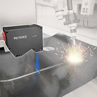
Non-contact-type surface inspection with a laser displacement sensor
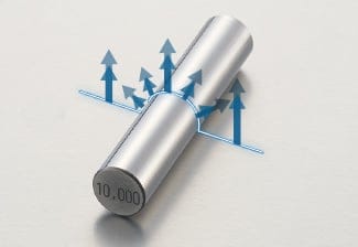
The bead shape is detected based on the reflection of the laser emitted to the weld surface.
Laser displacement sensors generally require an optimum amount of reflected light to ensure stable shape detection. Conventional typical laser displacement sensors adjust the amount of light for a target based on the intensity of the received light reflected from the entire surface of the target. Consequently, they had problems with erroneous detection caused by the difference in the reflected light when measuring curved surfaces and surface with different colors.
The LJ-X8000 Series High-speed 2D/3D Laser Scanner detects the shape of the bead by emitting a line laser from the sensor head and using the light-section method that measures the cross-sectional shape based on the reflected light. Its light receiving element with a dynamic range 2400 times wider than conventional models enables accurate profile recognition even when the target weld has a curved surface, gloss, or color irregularities.
The compact sensor head capable of high-speed sampling is suitable for inline measurement.
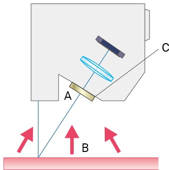
Detection mechanism of the light-section method
Laser light is spread into a wide beam by a cylindrical lens and diffusely reflects on the surface of the target. This reflected light is focused into an image on the HSE3-CMOS, providing high sensitivity and wide dynamic range. This image is used to detect the changes in position and profile and measure the displacement or shape.
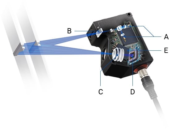
- Semiconductor laser
- Cylindrical lens
- 2D Ernostar lens
- HSE3-CMOS
- GP64-Processor
Wide dynamic range ensuring stable detection
Conventional displacement sensors required the adjustment of the laser power or exposure time when the reflected light fluctuated. The LJ-X8000 Series has a wide dynamic range to allow accurate profile recognition without being affected by the difference in the reflected light intensity caused by the inclination or gloss of the measurement surface.
Profile detection with the LJ-X
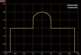
Profile data not affected by brightness difference
Blue laser not affected by hot targets
Typical red laser displacement sensors have a band-pass filter in front of their receiver that passes light of around 650 nm only. When the target is a red-hot steel plate, the wavelength components of the radiant light are mostly between red and infrared. This means that the detection is greatly affected by the ambient light.
The LJ-X8000 Series has adopted a blue laser and is equipped with a band-pass filter that passes light of around 405 nm only. This allows measurement of even hot targets immediately after welding without being affected by wavelength components between red and infrared.
- Reflected blue laser light
- Radiant light from hot targets
(including many wavelength components between red and infrared) - Band-pass filter passing light of around 405 nm only
(preventing the influence of the wavelength components between red and infrared)
Unlike conventional cameras or typical laser displacement sensors, the LJ-X8000 Series achieves stable profile detection without being affected by sparks or other optical noise generated during welding or the radiant light from hot-red steel plates immediately after welding.
This enables, for example, high-speed inspection of bead shape immediately after welding by tracking the torch in the welding process of tailored blanks (TBs).
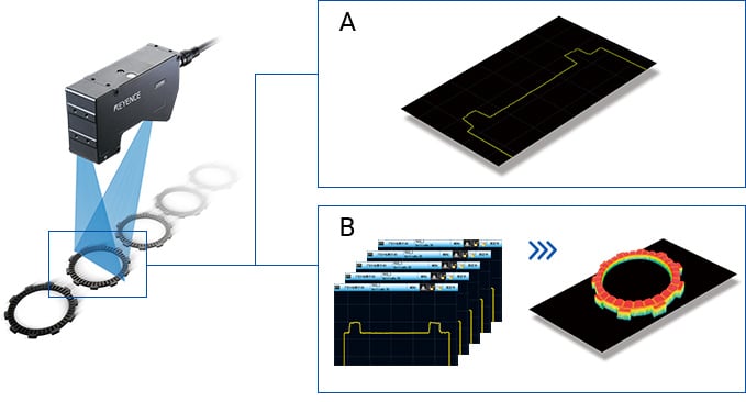
- Comparison of bead shape detection in tailored blank welding
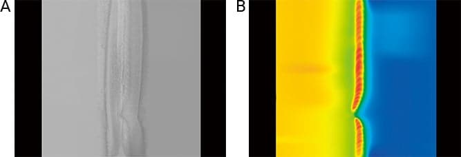
- A. Conventional camera
- Measurement was difficult due to unstable surface conditions such as color irregularities and gloss of the target.
- B. Laser displacement sensor (LJ-X8000 Series) + Image processing
- Bead shape can be measured stably without being affected by the surface condition of the target.
In this way, the LJ-X8000 Series allows non-contact measurement of intact shape of weld beads. This can be applied to:
- 2D shape inspection for defective weld beads (such as undercut, overlap, insufficient reinforcement, or cracking)
- 3D shape inspection using image processing and analysis of continuous cross-sectional shape data to achieve further detailed inspection such as finding minute surface defects.
- Examples of 2D/3D shape inspection using the LJ-X8000 Series