Groove welding basics and cautions
There are many different types of welding methods, including fillet welding, spot welding, and plug welding. To create welds that must be stronger than with other methods, however, groove welding is often used. Groove welding uses a process known as “grooving” to join base metal surfaces together.
This page introduces basic knowledge such as the names and welding symbols for each part of the groove, differences with fillet welding, how welds relate to strength, and the defects that can occur with groove welding.

- Grooving
- Butt welding and groove welding
- Differences with fillet welding
- Groove names and symbols
- Differences in penetration according to groove shape
- Groove welding inspection and problems
Grooving
Groove welding is used to create a beveled opening in a weld joint before welding to achieve the necessary penetration. The process of creating the bevels is known as groove machining, and welding the beveled surfaces together is known as groove welding.
Full-penetration groove welding
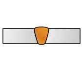
Groove welding is an essential welding technique for situations where deformation of the base metals must be limited and high-strength welding is required. Grooving increases weld strength by enabling full-penetration welding, making groove welding widely used in various applications, especially when arc-welding thick plates.
Groove welding is also effective for laser welding, which has narrower weld lines than arc welding, as groove welding allows for narrower weld lines and lower heat input, helping to suppress deformation and residual stress in the base metal. However, because the weld line is narrower than with fillet welding, higher accuracy is required during groove machining and in tracer control during welding.

Butt welding and groove welding
Butt welding is used to join two base metal surfaces along the same plane.
In addition to joining flat plates, butt welding is also used for piping and other similar applications. With butt welding, a thin backing metal (backing iron) is applied to the surfaces being joined. Unlike with fillet welding, butt welding integrates the joined base metals. This allows for stronger weld metal and heat-affected zone than the base metal, such as with structural steel, resulting in a stronger joint.
However, achieving full-penetration welds is often difficult with butt welding. This is particularly true for thick plates. To solve this problem, full-penetration welding is often performed by beveling the joint surfaces and using groove welding.
Differences with fillet welding
With groove welding, the joint strength can be adjusted by changing the shape of the bevel to alter the depth, width, and joint area of the weld. Fillet welding is not as strong because of the gaps between the base metals.
For sheet metal welding, both groove welding and fillet welding are used depending on the area being welded. Full-penetration welding offers the greatest strength increase for groove welding, and this method is often used for welding strong components because the achieved strength is equivalent to that of the base metal.
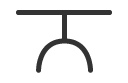
T-joints
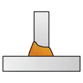
Groove welding
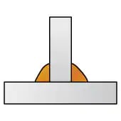
Fillet welding
Groove names and symbols
Each part of the groove has a specific name, and each groove shape has a specific symbol. This section introduces the names, symbols, and characteristics of the most commonly used grooves in groove welding.
Names
Of the many different groove types, this section uses a V-shaped groove as an example for introducing the names of each part.
V-shaped groove
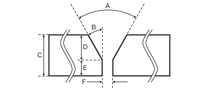
- A
- Groove angle
- B
- Bevel angle
- C
- Plate thickness
- D
- Groove depth
- E
- Root face
- F
- Root gap
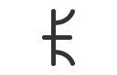
Reading groove welding symbols
The welding symbol defines the shape of the groove. For example, the following shows a full-penetration weld with a welding depth of 5 mm (0.20”), a root gap of 0, and a groove angle of 70°.
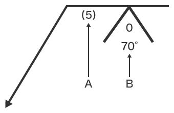
- A
- Weld depth
- B
- Root gap, groove angle
Groove types and symbols
Grooves can be made into a wide variety of shapes for increased strength. The shape of the groove to be used will depend on the base metal material, thickness, and welding location.
| Groove cross-sectional shape | Welding symbol | Characteristics | |
|---|---|---|---|
| Square groove | 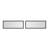 |
 |
Used between flat cross-sectional shapes, this groove shape offers easy groove machining. The small welding amount also results in less deformation. Generally, square grooves with a gap of 0 mm (0.00”) are used for electron beam welding, laser welding, and friction stir welding (FSW). This shape is difficult to use with thick plates. |
| V groove* | 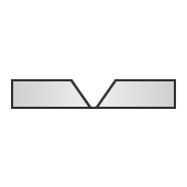 |
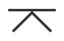 |
This groove has a V-shaped cross-section, and groove machining is relatively simple. Angular deformation can be significant due to an asymmetric bead shape in the plate thickness direction. Because the welding amount increases with thicker plates, deformation also increases. |
| Bevel groove | 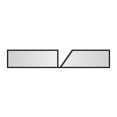 |
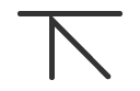 |
This groove shape has beveling on one side only. Groove machining is relatively simple, but the bevel angle and root gap will affect the workability of the weld. |
| J groove | 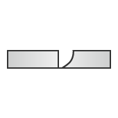 |
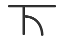 |
This groove has a J-shaped cross-section. Unlike a bevel groove, one side of the base metal is rounded, making groove machining difficult. |
| U groove | 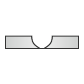 |
 |
This groove has a U-shaped cross-section, and because each side of the base metal is rounded, groove machining is difficult. The welding amount can also be reduced for extremely thick plates, ensuring less deformation. |
| Double-V groove | 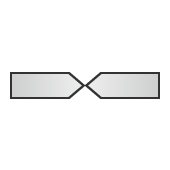 |
 |
Groove machining for this shape is difficult, and compared with a V groove, the welding amount can be reduced for less deformation. |
| Double-bevel groove | 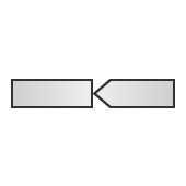 |
 |
Groove machining for this shape is simple. Although similar to a double-V groove, the asymmetrical groove makes welding and back-chipping difficult. |
| Double-J groove | 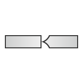 |
 |
Because each side of the base metal is rounded, groove machining is difficult for this groove shape. The characteristics are similar to those of V and double-V grooves. The welding amount can also be reduced for extremely thick plates. |
Thick plates: Steel plates with a thickness of 6 mm (0.24”) or more
Ultra-thick plates: Steel plates with a plate thickness of 150 mm (5.91”) or more
* Sometimes called a Y groove if the root is large.
Differences in penetration according to groove shape
Of all the groove welding types, square grooves are the easiest to machine and also have a low welding volume with minimal heat deformation. However, there is a limit to how thick the plates can be for full penetration. V and U grooves, on the other hand, can be used for full penetration even with thick plates and with no theoretical upper thickness limit.
The following examples highlight the difference in welding between square grooves and V grooves.
The welding conditions are as follows.
Welding method: TIG welding
Plate thickness: 7 mm (0.28”)
Output: 120 V (square groove) / 100 V (V groove)
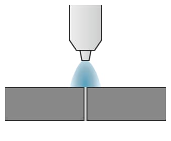
Penetration with a square groove
Square groove welding is done without altering the plate thickness. This means the arc does not penetrate to the other side of the plate, resulting in partial welding of only about half the plate.
During welding
After welding
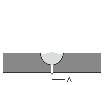
- A
- No penetration
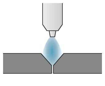
Penetration with a V groove
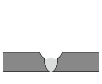
For V groove welding, the plates are machined before welding is performed. This allows the arc to penetrate to the other side of the plate. The bead created on the opposite side of the weld is called the back bead. However, because the top surface of the plate becomes depressed, a second layer is welded to ensure sufficient strength. This results in full-penetration welding.
1st layer welding
During welding
After welding
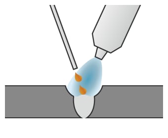
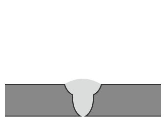
2nd layer welding
During welding
After welding
Groove welding inspection and problems
The groove shape will have a significant effect on the ease and strength of welding as well as the welding amount. Although groove machining is done with a cutting machine, if the groove angle, root gap, gap in the backing metal, and other factors are not appropriate, welding defects can arise.
For example, the welding amount can be reduced by reducing the cross-sectional area of the groove, but if the welding amount is too small, tracer control becomes difficult and welding defects will be more likely to occur. On the other hand, although a wider groove will make tracer control easier, the welding amount will become higher and weld deformation will increase, leading to welding defects. These welding defects are caused by improper welding of parts that should be welded together, poor groove shape, insufficient heat input for the groove shape, or poor bead shape in previous passes.
This section introduces the main inspection points to consider with groove shapes and the problems with groove welding.
Groove shape inspection points
Problems with groove shapes generally occur in the groove machining process. Groove shape inspection items include the groove angle, root face and gap, and butt joint alignment. Inspecting these items before performing welding can prevent welding defects from occurring. Groove machining can be done with thermal cutting using gas or a laser, or mechanical cutting using a cutting machine. The groove shape inspection points will vary depending on the groove machining method used.
- Thermal cutting
- Because this machining method uses heat, the base metal may expand or contract during heating or cooling, which could change the groove dimensions. Be sure to measure the groove angle and root gap to verify that they meet the required dimensions. It is also important to check for slag adhering to the surfaces of the groove.
- Mechanical cutting
- Creating grooves mechanically by cutting or machining can result in lamination on the cut surface or deformations on strained areas. Be sure to measure the bevel angle, root width, and other factors to verify that they meet the required dimensions. The bevel surface should also be inspected for roughness.
In addition to the above, assembly accuracy and the overall dimensions of the base metal are also important points to inspect. These inspections can be performed with welding gauges, scales, and straight edges. For mass production and micro-welding, however, inspections are generally performed using measuring instruments that can measure the groove shape in 2D or 3D.
Welding defects due to poor groove shape
An incorrect groove shape can result in welding defects. The following table introduces various welding defects and the groove locations that should be inspected if such defects occur.
| Welding defect | Groove area | Problem |
|---|---|---|
|
Root face |
Too large |
|
Too small | |
|
Using a backing metal | |
|
Groove angle/ bevel angle |
Too narrow of an angle |
|
Too wide of an angle | |
|
Using a backing metal | |
|
Root gap | Too large |
|
Backing metal | Too large |


