
Dimensional Measurement of Centrifugal Pumps

It is a common misconception that the shipbuilding industry is old and resistant to change. Actually, this industry is constantly looking to change in various ways such as by being thoughtful regarding the environment and introducing energy-saving technology. Although ships are loaded with many pieces of equipment, the pumps that transport fuel oil, lubricating oil, etc. and that adjust the ballast water are important devices that have a direct impact on the operation efficiency of the ship.
There are many types of pumps used on ships, but this section focuses on centrifugal pumps, which have significant requirements for part accuracy. This section introduces basic knowledge such as the structure and functions of centrifugal pumps, the problems of dimensional measurements of the important parts, and the optimization of these measurements.
- What Is a Centrifugal Pump?
- Centrifugal Pump Structure
- Centrifugal Pump Applications
- Necessity of Dimensional Measurement of Centrifugal Pumps
- Dimensional Measurement of Centrifugal Pumps
- Problems of Dimensional Measurement of Centrifugal Pumps and Their Solutions
- Optimization of Dimensional Measurement of Centrifugal Pumps
What Is a Centrifugal Pump?
Centrifugal pump is the name given to pumps that use centrifugal force. They are one type of non-positive displacement pump, which confers energy to the fluid via rotation of an impeller, and can be used with a wide variety of fluids ranging from those with low viscosity such as water and volatile oil to those with high viscosity such as oil. These pumps can even be used with slurries and similar fluids.
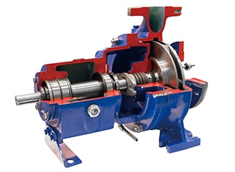
Centrifugal Pump Structure
A centrifugal pump transports fluid by driving the impeller inside its casing via a motor. Different structures lead to many different types of centrifugal pumps, but typical types are volute pumps and turbine pumps, which are used for different purposes according to the required lifting height.* This section explains the structures of these pumps.
* Lifting height: the height that fluid is pumped up by the pump.
Volute pump
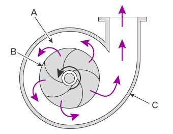
- A
- Volute
- B
- Impeller
- C
- Casing
In a volute pump, fluid flows into the impeller inside the casing, pressure is applied by centrifugal force, and this transports the fluid. The fluid that comes out of the rotating impeller decelerates gradually as it passes through the casing, and this speed is converted to pressure. This pump is used in facilities with relatively low lifting heights such as 20 m (65.6′) or less.
Turbine pump (diffuser pump)
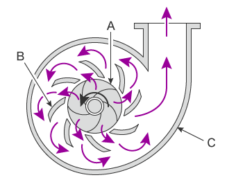
- A
- Impeller
- B
- Guide vane (diffuser)
- C
- Casing
Turbine pumps are also called diffuser pumps. Guide blades known as guide vanes (diffusers) are installed on the outside of the impeller of a volute pump to optimize the influx of the fluid to the impeller, resulting in a pump that increases the pressure more efficiently to transport the fluid. There are also types that can change the angles of the guide vanes to the optimal values. This pump can even be used in facilities with lifting heights greater (20 m to 30 m) (65.6′ to 98.4′) than those provided by volute pumps.
Centrifugal Pump Applications
Centrifugal pumps are capable of a wide range of lifting heights, so they are used in many operations on ships. Among these pumps, ballast pumps, which bring in and discharge ballast water, and cargo pumps, which transfer fluid and gas from cargo tanks to on-shore facilities, are important pieces of equipment.
Ballast pump
Ballast pumps bring water in and discharge water from ballast water tanks. Ships adjust their draft by increasing and decreasing their volume of ballast water in these tanks to match the weight of their cargo, the depth of water along their course, and changes in the weather. This process allows ships to navigate while maintaining the ideal buoyancy and piloting in a variety of situations. Large-scale ships have a ballast water volume of millions of gallons, and the draft depth greatly affects the piloting. Therefore, ballast pumps require not only the ability to operate at high speed and with high accuracy but also to have safety that allows for reliable operation.
Cargo pump
Cargo pumps transfer crude oil, LPG (Liquefied Petroleum Gas), and similar substances from cargo tanks to on-shore facilities. They are an important piece of equipment during tanker loading and unloading, and many tankers use a centrifugal cargo pump for the main pump. LPG tankers use pumps known as a submerged pumps and pumps with built-in motors. A submerged pump is installed at the base of a cargo tank and is submerged in LPG fluid. Hence, these pumps can withstand low temperatures of tens of degrees Celsius on the negative side.
Necessity of Dimensional Measurement of Centrifugal Pumps
The equipment on ships is most commonly used in situations, such as when the ship is in motion or in port in a foreign country, where it cannot be immediately repaired. It is also difficult to obtain replacement parts in these situations. Therefore, the most required features of this equipment are consistency and durability. For pumps to meet these requirements, they must be assembled precisely from parts machined with high accuracy.
Pumps comprise a large number of parts including a shaft that rotates at high speed and the impeller attached to it, the diffusers on the outside of the impeller, and the casing cover that encloses these parts. A pump will not exhibit the performance in its specifications if there are any deviations in the shaft accuracy or the clearance of the impeller and diffusers. Also, inaccuracies in factors such as the positions of holes for foundation bolts used to secure the pump to its stand, the shaft height, and the flatness/perpendicularity of the surfaces of flanges that join to valves and similar parts may lead to breakdowns in pumps that operate with high-speed rotations.
Consequently, to ensure that the functions required by on-ship pumps are met, it is vital to measure the machining and assembly accuracy of pump parts as well as the accuracy of the installation on the ship. Also, it is common for the measurement points to be written on standard diagrams, but the number of these points is enormous, so measurement requires thorough optimization.
Dimensional Measurement of Centrifugal Pumps
The casing cover is an important part of a centrifugal pump. It is also important to check that the gasket seating of the flanges that join to valves and similar parts as well as the shaft alignment that ensures normal operation of an installed pump are appropriate.
This section explains points to pay attention to when performing these measurements.
Casing cover dimensional measurement points
The casing cover is the part that covers the apertures of the casing. The casing cover is bolted to the casing, pinching between these two parts the casing gaskets that prevent fluid from leaking from the casing.
The casing gasket material determines the minimum design tightening pressure and the gasket factor, and these values determine the thickness of the casing cover and the number of bolts required to attach the casing cover. Furthermore, the casing cover dimensions greatly affect the volute shape and the clearance from the impeller, so these dimensions must be measured accurately.
Gasket seat dimensional measurement points
Pumps are connected to pipes, valves, etc. by flanges. Fluids are transported through pipes, and the amount of fluid is adjusted via the opening and closing of valves. There are many types of valves, and butterfly valves are commonly used when the aperture is large.
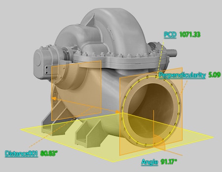
The fluid applies a large pressure to the gasket seat of the flange that joins the pump to a pipe or valve, so an important point regarding measurement is the accuracy of factors such as the P.C.D. (Pitch Circle Diameter) of the bolts that attach the flange and the flatness of the gasket seat. Because gaskets are sealed by surface pressure, gasket seats are a notable cause of fluid leaks, which occur when the machining accuracy is low.
Shaft alignment measurement points
Shaft alignment refers to the measurement and correction of misalignment in the positions of the motor shaft and pump shaft when joining these shafts together to transmit motive power from the motor shaft to the pump shaft. If shaft alignment is not performed, vibrations will be caused by eccentric rotation, leading to malfunctions in the bearings that support the shafts, the connected motor, and similar parts.
Flanges are commonly used to join pump and motor shafts. Therefore, the points to measure include the level differences and angles of the outer circumferences of flanges and the coaxiality and runout of shaft cores. Other key points include the measurement of the stand height and parallelism during installation.
Problems of Dimensional Measurement of Centrifugal Pumps and Their Solutions
For centrifugal pumps and other equipment installed on ships, it is important not just to perform dimensional measurements during machining but also to measure items such as the installation positions and angles during construction. Conventionally, these measurements were performed with calipers and tape measures, and errors during installation were corrected by inserting tapered liners. However, measurement and adjustment took a long time and it was not possible to determine the reference surface. These are the problems with this conventional method. Also, it is not possible to directly measure 3D shapes with hand tools such as calipers and tape measures. Therefore, the dimensions of 3D shapes were obtained with calculations from the values of the measurable points. The need to perform these calculations is the fundamental problem with this conventional method.
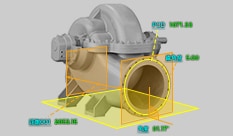
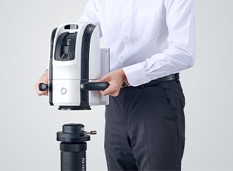
To solve these problems, the latest CMMs are used in an increasing number of cases. KEYENCE’s Wide Area Coordinate Measuring Machine WM Series enables high-accuracy measurement of large-scale targets such as the ballast pumps and cargo pumps on ships with the wireless probe. Even recessed areas of impellers and casings can be reached with no movement restrictions within the measurement range, which allows for easy single-person measurement with the simple operation of touching targets with the probe. Unlike measurements using measuring instruments such as calipers and tape measures, results do not vary, enabling quantitative measurement.
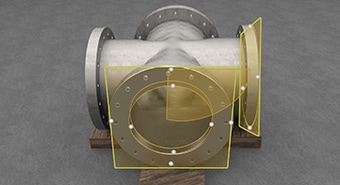
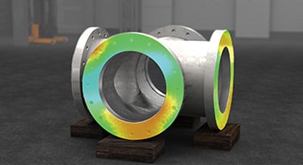
Dimensional measurement of the maximum dimensions and thickness of casing covers
Normally, two or more people use calipers and tape measures and work together to measure the large-scale casing covers of centrifugal pumps for ships. Additionally, the large number of measurement points makes these measurements require a lot of time.
However, the WM Series makes it possible for one person to complete these measurements easily and quickly. Also, the intuitive operation of just touching the wireless probe to the measurement point makes it possible to measure not only the maximum width and height of the casing cover but its recessed areas too. The P.C.D. (Pitch Circle Diameter) of the bolts that attach the casing and the perpendicularity of the gasket seats can also be measured. Additionally, the WM Series is portable and thus can make 3D measurements of the machining accuracy of machine tools, which is impossible with ordinary CMMs.
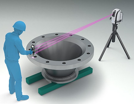

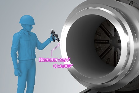
Dimensional measurement of valve gasket seats
Generally, large-scale valves are cast, and then additional machining is performed to finish the surfaces that require accuracy. Before setting a valve on a machine tool after casting, it is necessary to perform dimensional measurements for the leveling of the base and for axis adjustment for machining as well as to measure the dimensions of the machining allowance. Additionally, important measurement elements after machining include gasket seat strain, flatness, bolt hole positions, and surface angles.
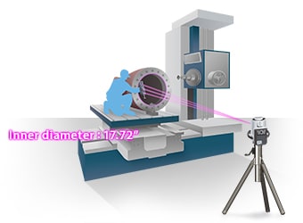
It is difficult to carry large-scale valves to bridge CMMs, so measurements are performed at the machining site with hand tools such as calipers and micrometers. However, it is not possible to measure dimensions and angles in 3D or dimensions that require virtual lines with these hand tools.
The portability of the WM Series allows it to perform measurements at machining sites. Because measurement points just have to be touched with the handheld probe, measurement can be performed by a single person.
Also, operations including comparisons against CAD data; GD&T such as flatness, perpendicularity, and position; and measurements using virtual lines can all be performed easily.
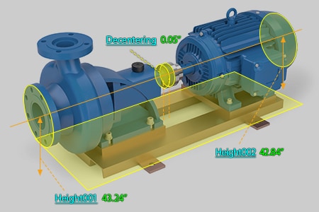
Measurement of shaft alignment
In shaft alignment, the shaft position is measured to check the shaft alignment status. The dimensional measurements in shaft alignment are operations during maintenance of installed pumps. Therefore, a measuring instrument that can perform measurements where the pump is installed is necessary.
A dial gauge is generally used for the measurement of shaft alignment, and the value on this gauge is used to check the shaft alignment status. However, this value varies greatly depending on factors such as how the dial gauge is attached and the size of the equipment, even if the shaft alignment status is the same. Also, it is necessary to consider deflection (droop) caused by gravity, so measurement must be performed by experienced personnel. In recent years, there have also been cases of measuring instruments and similar equipment specialized for shaft alignment using lasers.
The WM Series is portable and can be carried to the worksite in a suitcase to be assembled easily there at the start of measurement. A single person can measure a wide measurement range up to 25 m (82.0'′). The shaft alignment status can be determined accurately by measuring tilt angles and offsets in the horizontal and vertical directions. Furthermore, equipment that has an intermediate shaft has a large number of measurement points, which makes measurement take a long time. However, the WM Series enables fast measurement work with the simple operation of touching targets with the wireless probe.
Optimization of Dimensional Measurement of Centrifugal Pumps
The WM Series enables single-person measurement of the shapes of all the parts of centrifugal pumps for ships with the simple operation of touching targets with the wireless probe. In addition to the features introduced above, the WM Series has the many advantages listed below.
- Can perform in-machine measurement of large-scale products
- When chucked to a machine tool in a machining center or a similar location, the WM Series can also perform GD&T measurements such as of circles, distances, and angles.
- The portable body can be placed on-site
- The main unit can be carried around on the cart. Rather than having to move the measurement target, the WM Series can be brought to it.
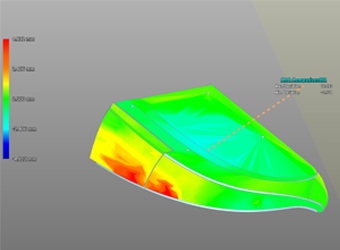
- Check with 3D CAD data
- Comparison measurements are possible between a part being measured and a shape imported from a 3D CAD file. The points of difference between the part and the 3D CAD data can be displayed as a color map. This allows for measurement of free-form curved surfaces and profile tolerances.
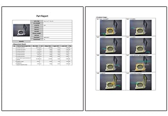
- Inspection reports can be created with photos
- Inspection reports can be automatically created with photos that allow you to understand measurement points at a glance. These inspection reports can not only gain you the trust of your business partners but also allow you to digitally save measurement results, leading to higher efficiency of in-house data management.
The WM Series provides powerful support for not just shape measurements of the parts of centrifugal pumps for ships and valves and shaft alignment measurement after installation but also for data analysis and inspection report creation. It dramatically improves the efficiency of manufacturing of centrifugal pumps and of work indispensable for their installation and maintenance.
