
Dimensional Measurement of Inspection Jigs for Large-scale Parts

The dimensional accuracy of inspection jigs greatly affects the efficiency of the dimensional inspection of parts. Conventionally, the shapes of inspection jigs were measured with hand tools, such as taper gauges and dial gauges, and the three-dimensional shapes of inspection jigs were measured with layout machines and arm coordinate measuring machines (CMMs). However, these measuring instruments were not sufficient to meet requirements such as larger inspection jig measurement and quicker construction while maintaining dimensional accuracy.
This section focuses on applications of inspection jigs required for measurement and on efficiency improvement of dimensional measurement of these jigs, which greatly affects inspection efficiency. The necessity of dimensional measurement of inspection jigs and measurement points are explained and efficiency improvement examples of these measurements are introduced.
- What Is an Inspection Jig?
- Dimensional Measurement Examples of Large-scale Parts Using Inspection Jigs
- Necessity of Dimensional Measurement of Inspection Jigs for Large-scale Parts
- Dimensional Measurement of Inspection Jigs for Large-scale Parts
- Problems of Dimensional Measurement of Inspection Jigs for Large-scale Parts and Their Solutions
- Optimization of Dimensional Measurement of Inspection Jigs for Large-scale Parts
What Is an Inspection Jig?

An inspection jig is used to inspect a part. They are used to check or verify the accuracy of parts such as their dimensions and shapes and are also referred to as gauges and CFs (Checking Fixtures). Inspection jigs are designed for various applications including dimensions, angles, shape, and fit, but they are all used to judge whether the dimensional tolerances and GD&T conform to the design values. There are also inspection jigs that are used to perform multiple inspections, such as dimensions and angles or shape and fit, at the same time with a single jig.
Commonly, inspection jigs are used for complicated shapes that cannot be measured with hand tools such as calipers and micrometers, thereby reducing variations in measured values and differences in the time spent between operators and allowing for efficient pass/fail judgment of parts. In this way, these jigs support stable line operation and cost reduction.
Dimensional Measurement Examples of Large-scale Parts Using Inspection Jigs
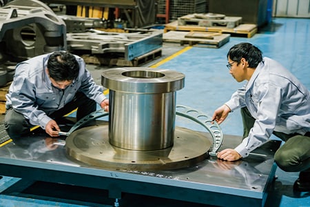
In dimensional inspections using inspection jigs, the part is positioned with items such as positioning pins (reference pins) and guides, and then the differences in the dimensions between the part and the inspection jig are measured. To position them, large-scale parts are clamped and secured in multiple locations other than the positioning pins and guides, and then the dimensions are measured. A different inspection jig exists for each part. These jigs are used in the measurements of various parts. This section introduces examples of dimensional inspections using inspection jigs. The examples refer to automotive parts.
Door frame
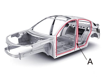
- A
- Door frame
The door frame is the window frame of the door. It has the roles of ensuring the rigidity of the body, holding glass, and preventing the intrusion of water. With a full panel door, the door frame is formed together with the door body, resulting in a panel with a large three-dimensional shape. Machining methods such as the tailored blank construction method and laser brazing welding are used in the manufacturing of door frames with full panel doors. Inspection jigs are used in inspecting the machining accuracy of these methods.
Side member
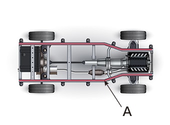
- A
- Side member
Placed on the left and right at the bottom of the body, side members provide the skeleton of the chassis. In the case of a vehicle with unitized construction, the side members are welded to the floor panel. A side member is constructed of a front side member, floor side member, and rear side member. The left and right side members are joined by way of a cross member, strengthening the body and providing torsional rigidity. The members are welded together, so the alignment of each member and their shape as an assembly are inspected.
Instrument panel
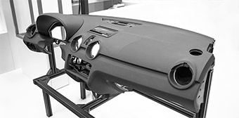
The instrument panel houses meters and air bag systems. Generally, this term indicates the entire panel, including the passenger side. In large-scale vehicles, the width of the instrument panel exceeds 2 m (6.6′). Most of these panels are large-scale resin molded products created by injection molding devices. Deformations may occur in these panels due to shape defects during forming or due to cooling after forming. Therefore, in the manufacturing of instrument panels for large-scale vehicles, inspections are performed to find warped and distorted shapes to prevent problems in the assembly during later processes.
Necessity of Dimensional Measurement of Inspection Jigs for Large-scale Parts
Some inspection jigs for large-scale parts are used to check and verify the accuracy of standalone parts. Some inspection jigs for large-scale parts are used to check and verify the accuracy of assemblies created from combinations of standalone parts.
In recent years, improvements in pressing technology and resin molding technology have led to increases in the size of standalone parts. Parts created by combining these standalone parts pose the problem of minor errors in each component part accumulating into a larger error in the final assembly. Hence, the dimensional and shape accuracy required of inspection jigs has also increased. It is vital to measure inspection jigs not only when they are manufactured but also periodically during use to check for dimensional and shape changes.
Dimensional Measurement of Inspection Jigs for Large-scale Parts
Because the position accuracy of an inspection jig is important, its GD&T must be measured at the same time as its dimensions. This section uses the measurement of an inspection jig for a part that has a free-form curve (such as a door frame) as an example to introduce important points.
Measurement points
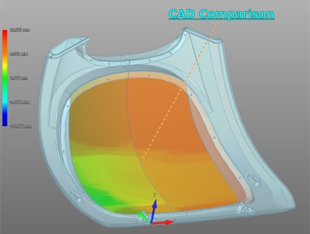
It is important to measure form tolerances such as the profile and flatness of the sections of the inspection jig that are in contact with the part. Also, with jigs used to inspect parts that are welded together, it is vital to measure values such as the positions and coordinates of the clamps and similar items. Furthermore, jigs used to inspect the shape of large-scale parts require shape accuracy that is at least as high as that of the corresponding part. A comparison with the CAD data is used to judge whether the measured values match the design values, and it is also vital to issue the inspection results for management purposes.
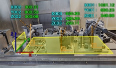
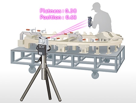
Frame measurement gauge profile measurement and CAD comparison
The profile of the frame measurement gauge, which secures the frame, is measured.
For example, in the case of a frame measurement gauge used to inspect a door frame, the length of one side is a few meters, so even a minor error interferes with the inspection and leads to inspection mistakes. Also, errors in the door frame will affect the operation accuracy of the door to be attached in a later process. Therefore, it is especially necessary to strictly measure the profile of the frame measurement gauge.
This statement also holds true for large-scale resin-molded products made from a large number of curved surfaces, and it is necessary to check the dimensional accuracy of each part, other than the profile, for the jigs used to inspect such products. One way to check this accuracy is with calculations via comparisons between the CAD data and digital data made from the differences between the measured values and the design values.
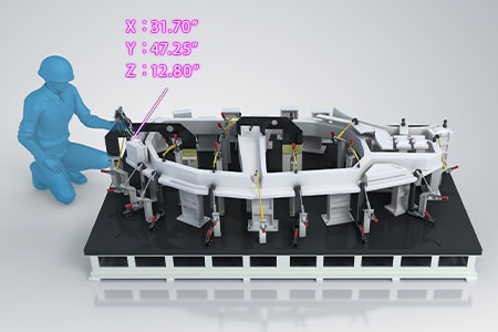
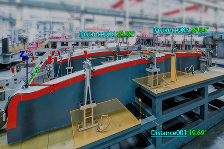
Inspection jig coordinate and position measurement
Inspection jigs for the frame, such as the side members, measure the coordinates and positions of the positioning pins and clamps. Low accuracy of the coordinates and positions of the positioning pins and clamps makes it impossible to measure the correct shape of the part. Especially with inspection jigs for frames assembled via welding, bolts, or similar methods, a small error can greatly harm the accuracy of the inspection jig. Therefore, an important point is checking that the coordinates and positions of the positioning pins and clamps are within their tolerances.
Issuing inspection reports
Inspection reports certify the quality of the finished product, certify that the delivered product has been finished to the requested dimensions, and certify that the product conforms to various standards. They also contain data such as the measuring instruments used in the measurement of the inspection jig and the measured values.
Simply by checking the inspection report, the product can be deemed to pass its inspection at the time of delivery, greatly reducing the amount of inspection work. The quality inspection method is directly linked to the amount of inspection work and its cost, so there is a major advantage to issuing an inspection report.
Problems of Dimensional Measurement of Inspection Jigs for Large-scale Parts and Their Solutions
The coordinates, positions, and profiles of positioning pins and clamps are important in the dimensional measurement of inspection jigs for large-scale parts. It is common for these measurements to require three-dimensional control items and accuracy on the order of micrometers, so there is a limit to how well hand tools can perform in these situations. Hence, layout machines and arm CMMs are widely used for these measurements.
However, it takes a lot of work to move large-scale parts from the manufacturing site to the layout machine where they can be measured. This method also poses the problem of being unable to measure promptly when on-site measurement is necessary. When an arm CMM is used, it needs to be moved during measurement due to its small measurement range. Furthermore, its operator must be highly skilled.

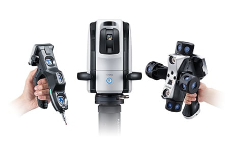
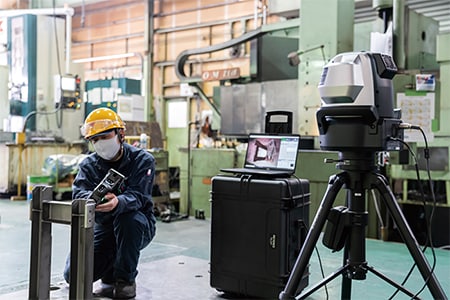
To solve these problems, the latest CMMs are used in an increasing number of cases. KEYENCE’s Wide Area Coordinate Measuring Machine WM Series enables high-accuracy measurement of position-related items for clamps and positioning pins attached over a wide area on inspection jigs with the wireless probe. Even recessed areas can be reached with no movement restrictions within the measurement range, which allows for easy single-person measurement with the simple operation of touching sections with the probe. Unlike measurements using hand tools such as tape measures, calipers, and dial gauges, results do not vary, enabling quantitative measurement. Additionally, dimensions can be measured directly in three dimensions on the basis of reference virtual lines, which ensures not only the dimensions but also the GD&T with high reliability.

Frame measurement gauge profile measurement and CAD comparison
The inspection jigs of large-scale parts are over one meter in size and use many free-form curves. Consequently, they are difficult to measure with hand tools. Also, differences in the dimensions between the inspection jig and its part are measured with taper gauges and feeler gauges. This is one example of how it is necessary to rely on inspections that depend on the techniques of skilled operators.
With the WM Series, it is possible for a single person to perform quantitative measurement with no variations by simply touching measurement points with the probe. The 3D position coordinates of each part of the inspection jig and its installation angle can also be measured by simply touching with the probe. Furthermore, the profile and similar items can also be measured with accuracy. This enables operators to measure important dimensions, which were measured using conventional measuring instruments, while intuitively checking measurement points on the monitor. The WM Series immediately saves the measurement results as data, enabling comparison measurement of measurement targets and shapes imported from a 3D CAD file and outputting of the measurement results as CAD data. Additionally, the WM Series is portable and thus can meet the need to measure 3D installation accuracy on-site, which is impossible with ordinary CMMs.
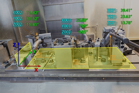
3D coordinate measurement of inspection jigs for automotive cast parts
It is difficult to use hand tools to measure cast automotive parts and other such large-scale parts that have irregular shapes, so dedicated inspection jigs are designed and created to ensure dimensional accuracy. Inspection jigs themselves have complicated shapes, so it is important to create them while determining the three-dimensional positional relationships between all the fitting parts.
With the WM Series, it is possible to easily measure the 3D coordinate positions even of large-scale inspection jigs with complicated shapes by simply touching measurement points with the probe. This measuring instrument is portable, allowing it to be set close to the site where the jig is being created, which enables on-site measurement to be started immediately. The measurement results are also displayed in real time on the small monitor on the probe, allowing a single operator to easily carry out measurements while instantaneously checking offsets from the design values.
Issuing inspection reports
The WM Series can use measurement results in inspection reports.
Including measured values and photographs of the measurement points in the inspection report makes the measurement situation very clear. These reports also greatly contribute to the simplification of confirmation work during delivery and acceptance of products.
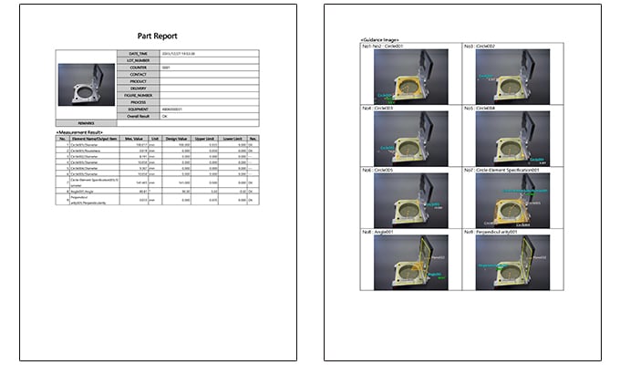
The WM Series automatically extracts the data required for quality management from the saved data, making it possible to easily check the measured values together with the images of the product that was measured. It can also automatically convert measurement results into inspection reports. Photographs are included in inspection reports, making them easy to understand. Also, because the rich text format (RTF) is used, users can flexibly edit these reports.
Optimization of Dimensional Measurement of Inspection Jigs for Large-scale Parts
The WM Series enables single-person measurement of inspection jigs of large-scale parts with the simple operation of touching targets with the wireless probe. In addition to the features introduced above, the WM Series has the following advantages.
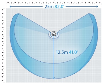
- High-accuracy measurement over a large area
- A wide measurement range up to 25 m (82.0'′) can be measured with high accuracy. The WM Series is equipped with the navigation measurement mode, which enables measurement at the same point according to a memorized measurement procedure, allowing anyone to obtain the same measurement data.
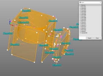
- Measurement results can be output as 3D models
- The measured elements can be exported as a STEP/IGES file. 3D CAD data can be created on the basis of the measurement results of an actual product even if no drawing is available.
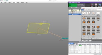
- Easy-to-understand interface
- CMM interfaces are often a mess of complex and unfamiliar commands. The WM Series provides intuitive operation using images and icons, so anyone can easily understand how to operate the system.
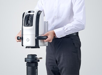
- The portable body can be placed on-site
- The main unit can be carried around on the cart. The WM Series can be brought into worksites and immediately measure the status of the work.
The WM Series strongly supports analysis, such as comparison with 3D CAD data, as well as dimensional measurement of inspection jigs of large-scale parts. It dramatically improves the efficiency of manufacturing of inspection jigs and of work indispensable for their installation and maintenance.
