
Dimensional Measurement of Conveyor Rollers and Frames

Conveyors are important transport devices vital to material handling systems. To allow for processing and assembly on conveyors, a high level of operation accuracy is required.
To realize this accuracy, a high level of dimensional accuracy is required. However, it takes a large number of personnel and a lot of work to measure conveyors with hand tools such as tape measures and calipers. It is also difficult to accurately measure the intended dimensions with these measurement methods, leading to the need for measurement methods with better efficiency and higher accuracy.
Conveyors are very diverse, so this section discusses the most general type of conveyor. This section introduces basic knowledge such as the structure and principles of conveyors, the problems of their shape and dimensional measurements that affect their performance, and methods for realizing measurements with better efficiency and higher accuracy.
- What Is a Conveyor?
- Types of Conveyors
- Conveyor Principles and Structures
- Conveyor Dimensional Measurement Points
- Problems of Dimensional Measurement of Conveyors and Their Solutions
- Optimization of Dimensional Measurement of Conveyors

What Is a Conveyor?
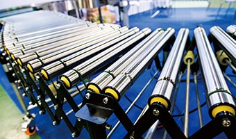
A conveyor is a machine that continuously transports loads. Some conveyors have the motive power to transport the transported items in a fixed direction at a constant speed and do so via methods such as motors, hydraulics, and magnets. Conveyors that do not have this motive power transport the transported items by inertia. Conveyors are installed between devices and processes and do not merely transport items. Processing and assembly may also be performed on items as they are transported.
Types of Conveyors
Conveyors with motive power include belt conveyors, motor conveyors, chain conveyors, screw conveyors, vibrating conveyors, and magnet conveyors. Roller conveyors are the typical type of conveyor without motive power.
Different conveyors are used depending on the required capabilities such as the size, weight, and material of the transported items as well as the usage environment. Conveyors are used to not just transport items in straight lines but also to change the transportation direction and to branch/join paths. Conveyors can be installed to match the available space and can sort the items they transport.
These conveyors transport items between devices and processes and may even transport items between material handling devices, so they have to be free of warpage and distortion. Also, conveyors require accurate positioning capabilities if they are transporting items that are being assembled or processed by automated machinery. Hence, conveyors require highly precise manufacturing technology and accurate installation, which means that dimensional measurement is vital in each process.
Conveyor Principles and Structures
Dimensional measurement of each part is vital during conveyor manufacturing and installation. Consequently, it is necessary to understand conveyor principles and structures. This section explains these principles and structures with the examples of belt and roller conveyors, which are general conveyors.
Belt conveyor
In a belt conveyor, the transport belt is attached so it wraps around the drive pulley. The drive pulley (head pulley) is connected to the drive motor and receives motive power from this motor, which changes the frictional force generated between the transport belt and the drive pulley into the driving force. Generally, a belt conveyor can receive the frictional force with a surface, which results in a large transporting force. Also, the transported items are set on top of the transport belt of the belt conveyor, so it can transport not only boxes and bags but powders and similar items as well. Also, the frictional force between the transport belt and the transported items is large, so tilted transport up and down slopes is possible through the use of slanted transportation belts.
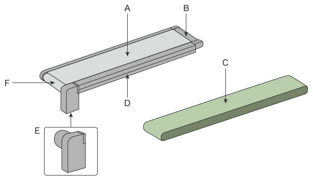
- A: Frame (transport belt support)
- The frame supports the transport belt. There are different types of frames such as those with support plates and those with rollers.
- B: Tail roller
- This roller on the driven side applies tension to the transport belt. It guides the transport belt and prevents it from meandering.
- C: Transport belt
- Transported items are placed on this part, which is commonly made of rubber or resin.
- D: Frame
- The pulley and roller are attached to the frame, the structure that provides the skeleton of the conveyor. Example frames include stringer frames, formed from steel material that is bent via pressing or shaped, and truss frames, formed from shaped steel material assembled into trusses.
- E: Drive motor
- This is the source of the motive power that moves the transport belt. Induction motors, brushless motors, and stepping motors are used. Some motors also have a function for adjusting the transport speed and an electromagnetic brake for stopping the rotation of the motor via electromagnetic force.
- F: Drive pulley (head pulley)
- This pulley is connected to the drive motor and drives the belt conveyor.
Roller conveyor
There are two types of roller conveyors: driving conveyors, which have motive force, and free conveyors, which do not have motive force. In a driving conveyor, the motive force of the drive motor rotates the transport rollers, which transports the items. The driving force is transmitted in many ways, but the principle of transporting items via the rotation of the transport rollers driven by a motor is the same. Items are transported by the frictional force between them and the transport rollers. However, a roller conveyor only contacts the transported items along a line, so the transporting force is smaller than that of a belt conveyor. A free conveyor, on the other hand, transports items via inertia applied by workers pushing the items or by devices known as pushers.
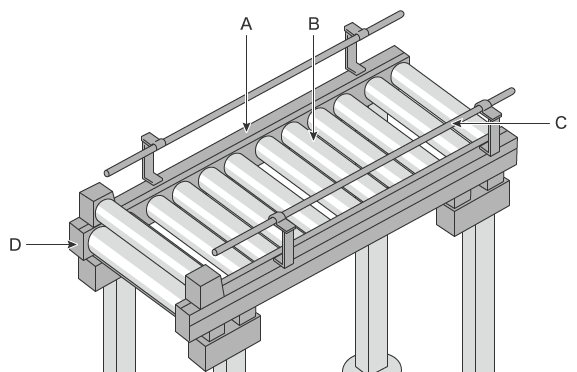
- A: Frame
- The rollers are attached to this frame. Example frames include stringer frames, formed from steel material that is bent via pressing or shaped, and truss frames, formed from shaped steel material assembled into trusses.
- B: Transport roller
-
Example: Belt driven 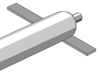
The rollers transport the items.
In a driving conveyor, rollers are connected to the drive motor via a belt, chain, etc.
Free conveyors come in roller types and wheel types and are used in situations where items are pushed by hand or move down slopes. - C: Workpiece guide
- Guides prevent transported items from falling off the conveyor.
- D: Drive motor (in a driving conveyor)
- This is the source of the motive power that moves the transport rollers. Induction motors, brushless motors, and stepping motors are used. Some motors also have a function for adjusting the transport speed and an electromagnetic brake for stopping the rotation of the motor via electromagnetic force.
Conveyor Dimensional Measurement Points
Conveyors are manufactured and assembled at factories before being installed at worksites. During manufacturing, the key point is to measure the roller pitch and frame dimensions with the conveyor in the same state as when it is installed.
Errors in the dimensions during manufacturing lead to a lot of work to make corrections after installation and may even require the conveyor to be returned to the factory for reprocessing and adjustment. Also, the key point during installation is to make adjustments while measuring how parallel and level the conveyor is to ensure that it operates normally.
Failing to correctly process and adjust the conveyor may lead to transport defects due to roller rotation defects and transport belt meandering.
Dimensional measurement points
The most important measurement points for a conveyor are the assembly accuracy of the rollers and the dimensions of the frame and head frame.
This section explains the key points for these two dimensional measurements.
Roller pitch and level
Generally, the pitch of rollers is determined so that items being transported are always in contact with 3 or more rollers. The roller pitch is calculated from the width, length, and weight of the transported items and is designed so the weight of the transported items is applied to all rollers evenly.
If the roller pitch is not even, the weight applied to each roller will vary, preventing smooth transportation and leading to belt meandering (in the case of a belt conveyor). Also, if the rollers are not level in relation to the floor, the path line will not be stable, which is a major problem for transportation between material handling devices.
Therefore, it is necessary to measure the roller pitch and level not only during manufacturing but during installation as well and to confirm that these values are within the tolerances for the design values.
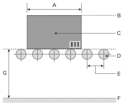
- A
- Length of transported item
- B
- Path line
- C
- Transported item
- D
- Roller
- E
- Roller pitch
- F
- Floor level
- G
- Roller level
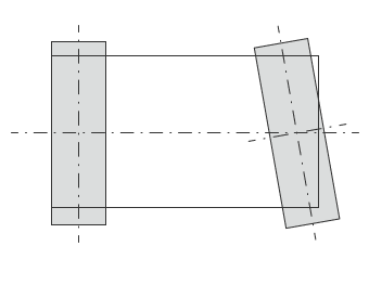
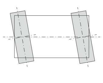
Frame and head frame
Bending, twisting, level defects, and misplacement of the frame and head frame lead to transport belt meandering and leaning. These issues cause not only transport defects but also greatly affect the durability of the conveyor.
Other causes of transport belt meandering and leaning include incorrect pulley parallelism, position, and angle. These defects can be corrected with adjustments. However, these adjustments are only possible if frame processing and assembly accuracy are obtained, so the flatness, parallelism, and curvature of the frame and head frame are important measurement points.
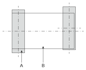
- A
- Roller
- B
- Transport belt
Problems of Dimensional Measurement of Conveyors and Their Solutions
It is important to confirm the accuracy not only when measuring the dimensions of a completed conveyor but also during its installation and maintenance. Especially vital dimensional measurements include the pitch and level of the rollers and the flatness, parallelism, and curvature of the frame. Conventionally, these measurements were performed using hand tools such as tape measures, levels, and dial gauges. However, there are problems with variations in measured values from measurer to measurer, difficulty to understand curvature tendencies, and long measurement time.
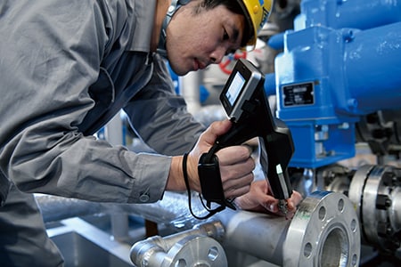
To solve these problems, the latest CMMs are used in an increasing number of cases. The wireless probe of KEYENCE’s Wide Area Coordinate Measuring Machine WM Series enables a single operator to perform high-accuracy dimensional measurement even of long conveyors. Even recessed areas of workpieces can be reached with no movement restrictions within the measurement range and dimensions can be measured with the simple operation of touching target points with the probe held in a single hand. Also, unlike measurements using hand tools such as tape measures, levels, and dial gauges, results do not vary, enabling quantitative measurement.

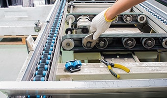
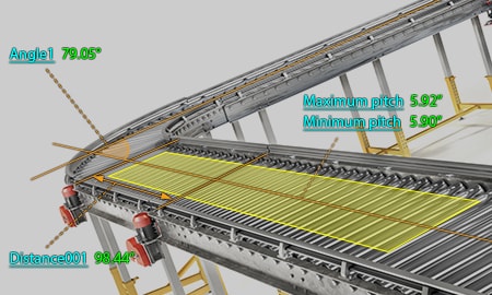
Roller pitch measurement
The larger the roller diameter, the smaller the coefficient of rolling friction, enabling more efficient transportation. However, larger diameters decrease the clearance between rollers. Hence, the rollers may come into contact with each other if the pitch is not accurate. Also, if the rollers are not level, the transported items and transport belt may meander and the weight applied to each roller may vary.
Conventionally, the roller pitch was measured one location at a time with hand tools such as calipers and micrometers, but the large number of measurement points led to a long measurement time. Measured values vary according to the angle and strength used to apply these tools to the target, which causes variations in measured values among operators.
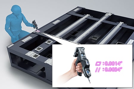
The WM Series enables the operator to perform measurements by simply touching the probe to the positions to measure. Simply by touching the target with the probe, the operator can measure not just the roller pitch but the parallelism between rollers and the level after installation as well. Even 3D distances and coordinates can be directly measured. This enables quick single-person measurement without variations in measured values among operators even when they are unfamiliar with measurement work.
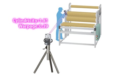
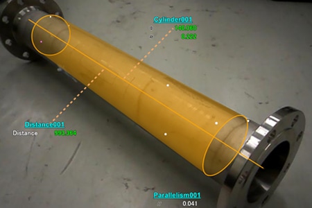
Flatness, parallelism, and curvature measurement of frames and head frames
The dimensional accuracy of the frame and head frame of a conveyor affects the assembly accuracy of all parts of the conveyor. Therefore, dimensional inspections are important not only during manufacturing but after installation as well.
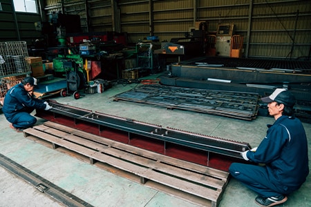
The conveyor, frame, and head frame dimensions were conventionally measured with tape measures. Also, because post-installation measurements are of long distances, length was measured with a laser length measuring machine and parallelism was measured with a level. However, multiple operators are required for such measurements, making them inefficient. What’s more, it was difficult to convert flatness and curvature to values.
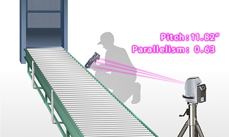
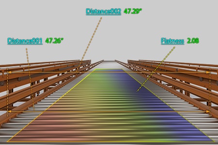
With the WM Series, even a single person can measure long conveyors. The accuracy is higher than that of a tape measure or laser length measuring machine, the flatness and curvature can be converted to values, and the distance between virtual lines can also be visualized. Also, warpage and curvature can be displayed with color maps, allowing dimensions to be corrected accurately and easily. What’s more, the portability of the WM Series allows it to be brought into worksites and immediately measure the installation status.
Optimization of Dimensional Measurement of Conveyors
The WM Series enables single-person measurement of the shapes and dimensions of the parts of long conveyors with the simple operation of touching targets with the wireless probe. In addition to the features introduced through the above examples, the WM Series has the following advantages.
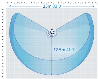
- High-accuracy measurement over a large area
- A wide measurement range up to 25 m (82.0'′) can be measured with high accuracy. The WM Series is equipped with the navigation measurement mode, which enables measurement at the same point according to a memorized measurement procedure, allowing anyone to obtain the same measurement data.
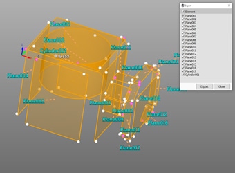
- Measurement results can be output as 3D models
- The measured elements can be exported as a STEP/IGES file. 3D CAD data can be created on the basis of the measurement results of an actual product even if no drawing is available.
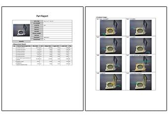
- Inspection reports can be created with photos
- Inspection reports can be automatically created with photos that allow you to understand measurement points at a glance. These inspection reports can not only gain you the trust of your business partners but also allow you to save measurement results as digital data, leading to higher efficiency of in-house data management.
- Easy-to-understand interface
- CMM interfaces are often a mess of complex and unfamiliar commands. The WM Series provides intuitive operation using images and icons, so anyone can easily understand how to operate the system.
The WM Series strongly supports analysis, such as comparison with 3D CAD data, as well as measurement of the dimensions and shapes of the parts of conveyors. It dramatically improves the efficiency of manufacturing of conveyors and of work indispensable for their installation and quality management.
