
Dimensional Measurement of Equipment Stands
Equipment stands are used as the foundation of various machines and pieces of equipment, protect devices from vibrations, and guarantee installation accuracy to ensure devices operate normally. The demands on their dimensions and strength are high, with special note being the equipment stands of large-scale equipment such as production devices and machining devices. These equipment stands themselves can be said to be excellent pieces of machining technology.
The term equipment stand is widely used and has many definitions. This section focuses on the large-scale equipment stands that are the framework of facility machinery and explains the basic knowledge of these stands as well as their dimensional measurement points, problems, and corresponding solutions. These dimensional measurements are the most important factor in ensuring the normal operation of the facility machinery that sits on equipment stands.
- What Is an Equipment Stand?
- Necessity of Dimensional Measurement of Equipment Stands
- Equipment Stand Manufacturing via Plate Working
- Dimensional Measurement of Equipment Stands
- Problems of Dimensional Measurement of Equipment Stands and Their Solutions
- Optimization of Dimensional Measurement of Equipment Stands
What Is an Equipment Stand?
Also known as facility stands, equipment stands are mainly used in large-scale facilities where they provide the framework that supports facility machinery such as semiconductor production devices, inspection devices, transporters, and machining devices.
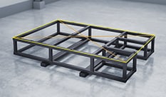
An equipment stand is constructed of a frame and a base plate that sits upon it. Because the frame must be rigid and strong enough to support the weight of facility machinery, it is mainly constructed of channel steel, angle steel, square pipes, or other high-strength materials. Also, the base plate must be machined with minimal strain and twisting to prevent part assembly errors.
Most facility machinery must not only be strong but also have accurate parallelism and verticality, so equipment stands require high dimensional accuracy. Furthermore, the Building Standards Act of Japan applies to equipment stands that exceed the defined scale.
Racks and reinforced concrete floors and beams are similar to equipment stands, but racks have simpler structures than equipment stands and support pipes and similar items required by facility machinery. Reinforced concrete floors and beams that hold facility machinery are commonly referred to as the facility foundation.
Necessity of Dimensional Measurement of Equipment Stands
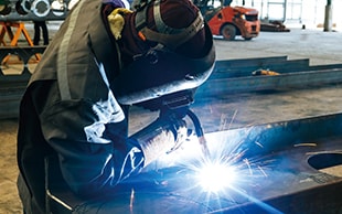
The welding accuracy when assembling processed parts greatly affects the dimensional accuracy and strength of equipment stands. Therefore, to ensure the performance of equipment stands manufactured via plate working, it is vital to use a welding method that corresponds to the materials and usage purpose.
For example, full welding is used to obtain strength where pieces of channel steel, angle steel, or square pipes are joined together to make an equipment stand. However, full welding has the disadvantage of making the material strain easily due to the welding heat. Therefore, countermeasures such as modifying the welding procedure and welding while cooling the welded part to minimize strain due to heat are necessary.
Also, thermal deformation and cracks may occur during processing to cut or drill holes into materials. Bending also requires delicate care, because changes in the frictional resistance that occurs between the plate and the die may change the bending position and angle. Errors in the bending position and angle make assembly via welding difficult. Equipment stands that require even higher accuracy undergo precision processing via lathes, machining centers, five-face milling machines, and similar instruments, but strict dimensional tolerances and GD&T must also be cleared at this processing stage.
In this way, equipment stands are manufactured via various types of processing during which there is a high chance that one or more parts is deformed, so it is necessary to measure a large amount of points. Also, two or three workers are required when measuring equipment stands, which are a few meters in size. Consequently, dimensional measurements of equipment stands must have few errors and good efficiency.
Equipment Stand Manufacturing via Plate Working
Equipment stands are assembled by welding together high-strength materials processed via bending, pressing, cutting, combining metal plates, etc. Assembled equipment stands are further finished to the accuracy required by the drawings with large-scale machine tools such as five-face milling machines.
This sequence of processes is referred to as plate working, and each process requires a high level of manufacturing techniques. Normally, drawings only list the size of the completed product, but the actual size of each part is important in plate working. An exploded-view diagram is created for each part, and their sizes are derived. The technicians who carry out this plate working are called plate workers, and they are required to obtain a wide range of manufacturing techniques including creating exploded-view diagrams, scribing, fusing, drilling, bending, welding, and finishing.
Dimensional Measurement of Equipment Stands
Equipment stands, which are the foundation of facility machinery, have strict dimensional accuracy requirements, but the important measurement points vary depending on the device. This section introduces the measurement points using as examples equipment stands for semiconductor production devices, which require strict dimensional accuracy and which have been developed at a remarkable rate among all production devices, and equipment stands for large-scale five-face milling machines.
Dimensional measurement points for equipment stands for EUV exposure equipment
EUV stands for Extreme Ultraviolet. EUV laser light has a wavelength of 13.5 nm, less than 1/10 the wavelength of conventional ArF excimer laser light, which is 193 nm. There are high hopes for the use of EUV in exposure equipment, masks, resists, and similar applications. Exposure equipment that uses EUV allows for processing with dimensions of 20 nm or less, which is difficult with optical lithography technology using ArF excimer laser light.
On the other hand, the increased detail of the processing dimensions makes the vibration-proofing function of the wafer stage and the alignment between exposure processes stricter than ever before. High accuracy is also required in the positional relationship with the FOUP (Front Opening Unified Pod) that inserts wafers into the exposure equipment.
With equipment stands for EUV exposure equipment, it is vital to measure the diagonal dimensions of the equipment stand frame, the allocation angle of the equipment stand holes, and the dimensions of the hole position equipment stand from the reference coordinates. The warpage, distortion, and flatness of the base plate are also vital measurement points. Special attention is required for these measurement points because their accuracy is linked directly to the yield rate and defect rate of semiconductor manufacturing.
Dimensional measurement points for equipment stands for large-scale five-face milling machines
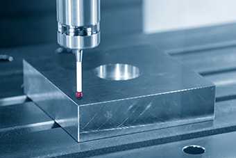
Large-scale equipment stands with complicated shapes or that require dimensions of ±0.01 mm (±0.0004″) and strict parallelism, flatness, etc. are processed with five-face milling machines. With these machines, the target remains stationary, and its front, back, left, right, and top surfaces are processed by the moving tool axis connector.
By nature, five-face milling machines are capable of processing with higher accuracy than three-axis machine tools. However, because the tool axis moves in complicated patterns through many processing axes, errors in the initial settings may cause greater processing errors with a five-face milling machine than with a three-axis machine tool. Especially when processing detailed or thin parts, deformation occurs due to processing pressure and heat, so measurement during processing is an important point.
Dimensional measurement during processing is referred to as in-machine measurement, and this is work that is vital to high-accuracy plate working.
Generally, in-machine measurement is performed by operators with hand tools or similar instruments, but variations occur in the measured values with different operators and different measurement points.
With a machine tool equipped with a measurement probe capable of in-machine measurement, it is possible to perform 3D dimensional measurement without variations, but errors occur due to the effect of the backlash of the machine tool and similar issues. Also, because the drive system of the machine tool itself is used to perform the measurement, it cannot be said that, in the true sense, objective measurement is performed. This is a fundamental problem.
Problems of Dimensional Measurement of Equipment Stands and Their Solutions
It is important to check the processing status of large-scale targets such as equipment stands not only after manufacturing but also during manufacturing. Conventionally, these measurements were performed with tape measures and calipers, and errors during installation were corrected by inserting shims. However, measurement and adjustment took a long time, resulting in longer periods before delivery and startup.
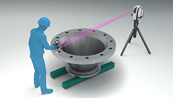
To solve these problems, the latest CMMs are used in an increasing number of cases. KEYENCE’s Wide Area Coordinate Measuring Machine WM Series enables high-accuracy measurement of large-scale targets such as equipment stands with the wireless probe. Even recessed areas of workpieces can be reached with no movement restrictions within the measurement range, which allows for single-person measurements with the simple operation of touching targets with the probe. Unlike measurements using measuring instruments such as calipers and tape measures, results do not vary, enabling quantitative measurement.
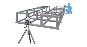
3D measurement of large-scale equipment stands
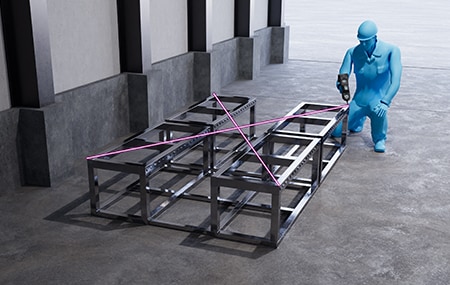
Normally, measuring a large-scale equipment stand with a tape measure or caliper takes a long time and requires at least two experienced workers. Also, only linear distances can be measured, not 3D dimensions or coordinate positions, which is a problem.
The WM Series allows for easy, single-person, 3D measurement of large-scale equipment stands. The intuitive operation of just touching the wireless probe to the measurement point allows the recessed areas of the target to be measured easily.
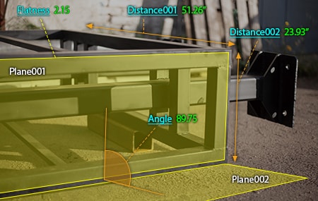
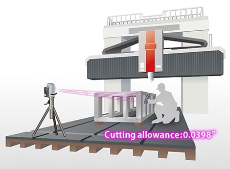
Fine dimensions in units of ±0.01 mm (±0.0004″) can be measured along with widths, heights, and diagonals, dimensions that are multiple meters in size. Hence, bending and pressing defects and even minor thermal deformations caused by drilling and cutting are caught, allowing for additional processing in problem locations before assembly.
Additionally, the WM Series is portable, so there is no need to place the target on the measuring instrument. Measurement can be performed with the target on the ground or a pallet. The ability to perform measurements at production sites, which is not possible with conventional bridge CMMs, allows the preparatory work for determining leveling and machining allowance to be carried out in advance, improving the operating rate of the machine tools.

Flatness and perpendicularity measurement of equipment stands for high-accuracy devices
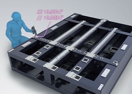
Typical equipment stand frames are manufactured using square pipes with thick walls and the aluminum main base installation areas are processed with a bridge machining center to be flat within a tolerance of 0.1 mm (0.0039″) or less to achieve necessary accuracy.
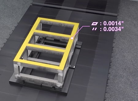
To obtain flatness, at least three points are measured on a target plane using tape measures or calipers and the maximum deviation is calculated as flatness. Alternatively, gaps generated when a target plane is placed between two parallel planes are measured using measuring instruments, such as feeler gauges, and OK/NG judgment is performed. However, it is impossible to accurately measure and quantify the flatness of 3D shapes, such as warpage and curvature.
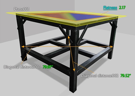
The WM Series enables accurate flatness measurement by simply touching a target plane with the wireless probe. It can also visualize strain and curvature of an entire surface in a color map, significantly improving efficiency of work that processes targets into intended shapes to complete them. Various other elements—such as perpendicularity, position, and parallelism—can also be measured. The WM Series greatly contributes to a higher quality of manufacturing of equipment stands.
Dimensional measurement performed on machine tools
Measuring a large-scale equipment stand with a bridge CMM requires the difficult work of removing the equipment stand from the machine tool and moving the stand to the metrology lab. Measurements performed on the machine tool with hand tools or the in-machine measurement function take an extremely long time, which decreases the operating rate of the machine tool. This is a problem.
Additionally, when equipment stands are fine-adjusted while the final accuracy is checked, it is preferable to measure their dimensions on machine tools instead of removing them. Therefore, for dimensional measurement of large-scale equipment stands, it can be said that the use of a CMM that is compact, portable, and capable of measuring a large area of an equipment stand set on a machine tool is ideal.
The WM Series can even measure the frames of equipment stands without having to remove them from large-scale five-face milling machines. It enables easy single-person measurement of dimensions such as diagonals of finished surfaces, increasing the efficiency of fine adjustments performed at the end of the manufacturing process.
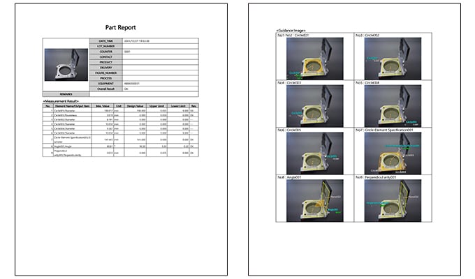
Furthermore, inspection reports with photographs of the measurement points can be created on-site, allowing the accuracy to be guaranteed with high reliability before product delivery.
Optimization of Dimensional Measurement of Equipment Stands
The WM Series enables accurate single-person measurement of the shape of large-scale equipment stands with the simple operation of touching targets with the wireless probe. In addition to the features introduced above, the WM Series has the following advantages.
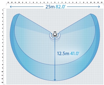
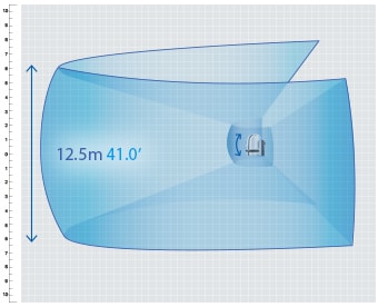
- High-accuracy measurement over an area up to 25 m (82.0'′) in size
- A wide range of up to 25 m (82.0'′) can be measured with high accuracy using the wireless probe. Large-scale targets whose measurement points cannot be reached with bridge or arm CMMs or with hand tools like calipers can be measured easily.
- Single-person measurement of large-scale products
- The easy operation of just touching the wireless probe to the point to measure enables single-person measurement of large-scale products, leading to major reductions in inspection costs.
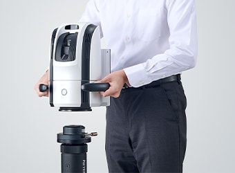
- The portable body can be placed on-site
- The main unit can be carried around on the cart. Rather than having to move the measurement target, the WM Series can be brought to it.
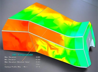
- Check with 3D CAD data
- Comparison measurements are possible between a part being measured and a shape imported from a 3D CAD file. The points of difference between the part and the 3D CAD data can be displayed as a color map. This allows for measurement of free-form curved surfaces and profile tolerances.
The WM Series provides powerful support for not just dimension and shape measurements of the parts of large-scale equipment stands and for measurement of the installation status but also for data analysis and inspection report creation. It dramatically improves the efficiency of manufacturing of large-scale equipment stands and of work indispensable for their installation and quality management.
