
Dimensional Measurement of Plant Piping Parts

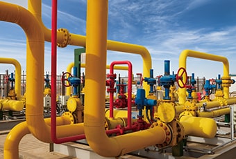
Piping supports many industries in the background, but at chemical plants, oil plants, power plants, and other plants in processing industries, plant piping takes center stage over other equipment and devices. Process piping is large-scale, using many pipes with large diameters and thick walls. Dimensional and shape measurement technologies are essential for manufacturing and construction of large-scale workpieces, and quick and high-accuracy measurement directly leads to more efficient manufacturing and construction.
This section explains basic knowledge of process piping, such as parts that constitute process piping and their roles, the necessity of dimensional measurement, and measurement methods. It also introduces problems with conventional measurement methods and solutions that can improve measurement efficiency.
- What Is Plant Piping?
- Plant Piping Parts
- Necessity of Dimensional Measurement of Plant Piping Parts
- Dimensional Measurement of Plant Piping Parts
- Problems of Dimensional Measurement of Plant Piping Parts and Their Solutions
- Optimization of Dimensional Measurement of Plant Piping Parts

What Is Plant Piping?
Plant piping is the piping that is installed and used in plants. Fluids flowing through plant piping include liquids such as tap water and sewage, gases such as steam and oxygen, and even powders. Fluids that are dangerous to human health may also flow through plant piping, so leakage from joints such as flanges and welded sections must be prevented. Additionally, parts and components that deliver fluids, such as pumps, motors, pressure gauges, and valves, are installed as part of piping routes, which requires consideration of the impacts of vibration, temperature, pressure, and other related phenomena. For these reasons, unlike piping for infrastructure, such as tap water, air conditioning, and sanitary equipment, advanced technology and high installation accuracy are essential for plant piping and high processing accuracy is required for components.
Plant Piping Parts
The function of piping is to deliver fluids from one place to another. To perform this function, the following elements are used to construct plant piping.
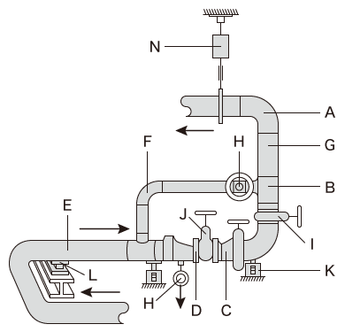
- Pipe joint
- A: Long elbow, B: Tee, C: Reducer, D: Flange, E: Bend, F: Short elbow
- Pipe
- G: Pipe
- Valve
- H: Globe valve, I: Gate valve, J: Control valve
- Hanger, support
- K: Variable support, L: Guide, N: Variable hanger
- Pipe joint
- Pipe joints are parts that allow pipes to follow intended routes. Pipe joints include reducers to change the pipe size, elbows to change the pipe direction, tees and crosses to join or divide fluid flows, and bends to gradually change the pipe direction.
- Pipe
- Pipes are made from various materials. For the steel pipes commonly used for plant piping, diameters and wall thicknesses are specified by the American Society of Mechanical Engineers (ASME). The outer diameter is called the nominal diameter. Pipes specified in units of millimeters are called Type A and those specified in inches are called Type B.
- Valve
- Valves are parts that regulate the flow rate by opening or closing a pipe. Valve types include gate valves, globe valves, butterfly valves, and ball valves.
- Flange
- Flanges connect pipes, pipe joints, valves, and other pipe parts. A flange is connected to another flange by tightening with bolts. A gasket is placed between the flanges to seal gaps between them.
Necessity of Dimensional Measurement of Plant Piping Parts
In plant piping, all parts are important and any faulty part can cause major issues. Flanges are not very noticeable among piping parts, but flanges are used widely throughout plant piping, and even small errors in their dimensions and shapes can cause installation errors and fluid leaks. This section explains the necessity of and reasons for dimensional measurement of typical flanges and bends used in plant piping.
Flange
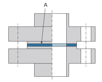
- A
- Gasket
A gasket is placed between flanges to ensure the airtightness of the joint between parts. Many flanges are used in plant piping because they are easy to disassemble, connect, and maintain.
Flanges are easy to disassemble, but they are also likely to be the source of leaks. Flanges are especially likely to allow fluids to leak when their shapes or dimensions are not accurate. For example, if a flange face is strained or bolt holes are misaligned, the gasket receives an uneven force, making it impossible to achieve the designed airtightness. Additionally, if a flange face angle is not as designed on the basis of the axial direction, the flange is difficult to install and could fail to lay the pipe along the designed route.
For the reasons above, high accuracy is required for flange shapes and dimensions, especially those installed in areas exposed to high pressure.
Bends
Bends are used to smoothly change the flow direction of a fluid. Bends are characterized by fluid delivery with low resistance, because their bending radii are approximately three to five times larger than their diameters, which is larger than the bending radius of elbows. Bends are created using the high frequency induction heating method, and low bending angle accuracy makes it difficult to connect them to other pipes and pipe joints. Bending angles need to be especially accurate when bends are joined to other parts by welding because high dimensional accuracy is required to ensure that they are properly engaged.
Dimensional Measurement of Plant Piping Parts
This section explains dimensional measurement points of plant piping parts.
Dimensional measurement points
The most important measurement points of plant piping parts are the dimensions and shape of flanges and the bending angle of bends.
This section explains the key points for dimensional measurements of these two parts.
Flange
Important measurement points of flange dimensions include the distance between flanges, the perpendicularity of flange faces to the flange axial direction, and the flatness of flange faces.
The perpendicularity of flange faces affects pipe installation accuracy. Even small errors in perpendicularity can cause large installation errors, especially when a long pipe is connected to a large diameter flange. A gasket is placed between flanges to join a part to another part with bolts. The bolts apply strong tightening torque to the flanges to press the gasket, which ensures airtightness. If tightened flange faces have defects, such as curvature, they may fail to press the gasket sufficiently. Flange dimensions and shapes need to be measured carefully because errors in these elements can lead to defective engagement, causing fluid leakage, which is a large problem.
Bend
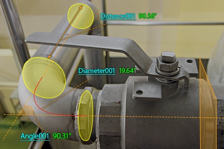
The diameter of bent sections and the bending angle of pipes are important dimensional measurement points of bends.
The diameter of a bend affects the resistance to fluid flow. Bends are created while yield stress is reduced by heating with high-frequency heating coils. If the diameter changes and the pipe is flattened, fluid resistance increases which can cause various problems. Additionally, low bending angle accuracy makes it impossible to install pipes along the correct routes. This may cause critical installation problems for large-scale plant piping. For the reasons above, errors in the diameter and bending angle of bent sections need to be strictly measured and inspected to prevent problems that may occur during and after installation.
Problems of Dimensional Measurement of Plant Piping Parts and Their Solutions
In plant piping construction, a lot of work is required to create pipes used in the on-site adjustment process, in which actual pipes are connected on site to determine the accuracy. Pipes used for on-site adjustment are manufactured using the following workflow: dimensional measurement (on-site), provisional manufacturing (pipe plant), installation check (on-site), manufacturing (pipe plant), and then installation (on-site). As shown above, information and pipes go back and forth between the installation site and pipe plant. Flange face inclinations and bolt hole position alignment also need to be considered during dimensional inspection, in addition to major measurement elements such as length and height. This requires special techniques with skilled workers, such as 3D measurement. If abnormal dimensions or shapes are found during this process, on-site dimensional measurement needs to be performed again, which can greatly impact the entire construction process. Improving dimensional measurement efficiency is an important issue in the pipe connection process.
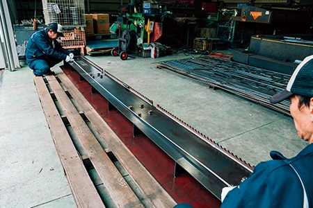
Dimensions are usually measured in this process using hand tools, such as dial gauges, tape measures, calipers, and right angle gauges. If 3D control items and accuracy on the order of micrometers are required, bridge coordinate measuring machines (CMMs) are used. Hand tools are easy to use for on-site measurement, but at the same time, require two or three people to measure piping parts larger than 1 m (3.3′), taking a lot of time and effort. If products are measured using a bridge CMM, they need to be moved from the manufacturing site to a measuring room and set on the CMM. It takes a lot of work to move and set products and measurements cannot be easily performed when and where they are needed.
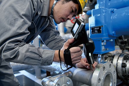
To solve these problems, the latest CMMs are used in an increasing number of cases. KEYENCE’s Wide Area Coordinate Measuring Machine WM Series enables a single person to perform high-accuracy dimensional measurement of large-scale piping parts with the wireless probe. Even recessed areas of workpieces can be reached with no movement restrictions within the measurement range, which allows for measurement with the simple operation of touching targets with the probe. Additionally, the WM Series is portable, allowing for measurements of any points when you want whether at manufacturing sites or installation sites. Unlike measurements using hand tools, measured values do not vary, enabling quantitative measurement.

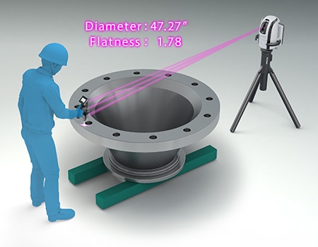

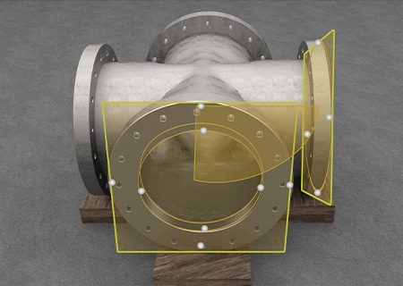
Measurement of internal diameter, plane-to-plane dimensions, plane angle, and inclination of flanges
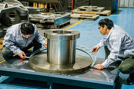
Large flanges can have outer diameters exceeding 1.8 m (5.9′), widths of 3 m (9.8′), and weigh around 4 t. Even for large flanges, a high level of measurement accuracy is required in many cases. The dimensions of large flanges, such as internal diameters, plane-to-plane dimensions, plane angles, and inclinations, need to be accurately controlled because they play important roles in the strength of joints.
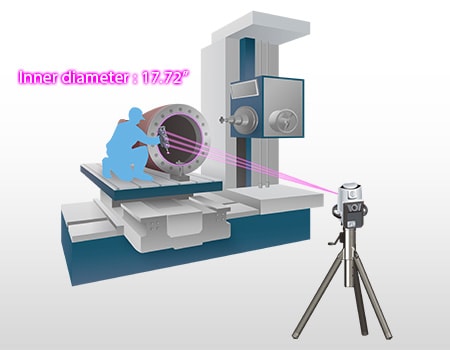
Dimensional measurement using dial gauges or tape measures requires at least two workers and it is difficult to perform accurate measurement because measured values vary every time measurement is performed. Accuracy of plane angles and inclinations is usually measured using right angle gauges or bridge CMMs. However, measurement using bridge CMMs presents many problems, such as the necessity of moving flanges to a measuring room and that it takes a lot of work to remove flanges from machine tools and then return them after measuring. Additionally, when piping parts are fine-adjusted while the final accuracy is checked, it is preferable to measure their dimensions on machine tools instead of removing them. Therefore, for dimensional measurement of large flanges, it is ideal to use a CMM that is compact, portable, and capable of measuring a large area of flanges set on a machine tool.
The WM Series can even measure large flanges set on machine tools without having to remove them. It enables easy single-person measurement of various elements, such as internal diameter, plane-to-plane dimensions, plane angle, and inclination of flanges, leading to more efficient fine adjustments of machining accuracy during manufacturing as well as ensuring the final dimensions. The WM Series also enables comparison measurement of measurement targets with shapes imported from a 3D CAD file and outputting of the measurement results as CAD data.
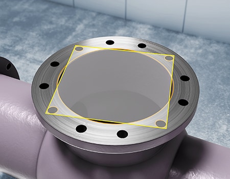
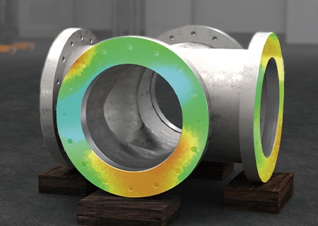
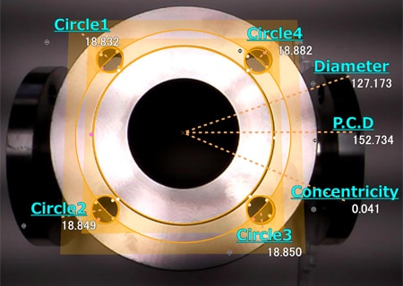
Measurement of flatness, screw hole pitch, and PCD of flange sealing surfaces
Flange sealing surface accuracy is checked by measuring flatness. It is also necessary to accurately control the pitch and pitch circle diameter (PCD) of screw holes used to joint flanges with other parts, because the accuracy of these dimensions greatly affects the strength of joints.
The flatness of sealing surfaces is checked by measuring multiple points using tape measures or calipers. This checking method is not truly accurate because defective dimensions in unmeasured areas are overlooked. Many points need to be measured to determine screw hole pitch and PCD, so at least two people and a lot of time are required to measure these elements using hand tools.
The WM Series enables easy flatness measurement by simply touching measurement points with the wireless probe and visual check of height differences using the color map display function. It also enables measurements of 3D elements, such as diagonal dimensions and plane angles, in addition to simple linear distances.
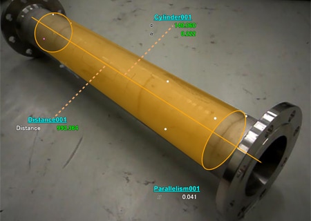
Bending angle and position coordinate measurements of bends
Unlike elbows, which are manufactured by molding in many cases, bends are created by bending them one by one. The bending angle, whether the cross-section is flattened, and other bending-related elements need to be inspected. Unlike elbows which have only short straight pipes, bends have long straight pipes, so the length of the straight pipe also needs to be inspected. In conventional inspection, dimensions are measured by multiple people using hand tools, such as tape measures and calipers. Bending angles are calculated and inspected by measuring pipe inclinations mainly using hand tools, levels, or angle meters. Cross-sectional deformation is calculated by measuring the distance between the pipe top and bottom and the distance between the right side and left side, height differences, and the internal diameter of the cross-section at the end of the bend. However, measured values vary according to the position at which hand tools, such as tape measures and calipers, are applied to the target, which makes it impossible to prevent variations in measured values among operators. It is also difficult to measure virtual distances and perform 3D measurements.
With the WM Series, it is possible for a single person to perform quantitative measurement by simply touching measurement points with the probe. Simply by touching the target with the probe, the operator can measure not just the straight pipe length but the bending angle and the cross-section deformed by bending. Even 3D position coordinates can be measured. Deviations from designed tolerances can also be judged instantaneously.
Optimization of Dimensional Measurement of Plant Piping Parts
With the WM Series, it is possible for a single person to measure the shape and dimensions of each section of plant piping parts with the simple operation of touching with the wireless probe. In addition to the features introduced above, the WM Series has the following advantages.
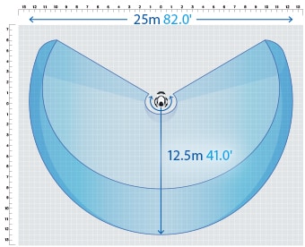
- High-accuracy measurement over a large area
- A wide measurement range up to 25 m (82.0'′) can be measured with high accuracy. The WM Series is equipped with the navigation measurement mode, which enables measurement at the same point according to a memorized measurement procedure, allowing anyone to obtain the same measurement data.
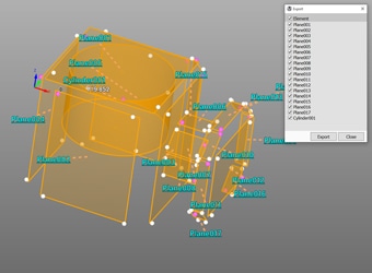
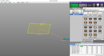
- Measurement results can be output as 3D models
- The measured elements can be exported as a STEP/IGES file. 3D CAD data can be created on the basis of the measurement results of an actual product even if no drawing is available.
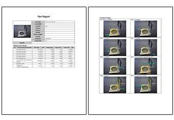
- Inspection reports can be created with photos
- Inspection reports can be automatically created with photos that allow you to understand measurement points at a glance. These inspection reports can not only gain you the trust of your business partners but also allow you to save measurement results as digital data, leading to higher efficiency of in-house data management.
- Easy-to-understand interface
- CMM interfaces are often a mess of complex and unfamiliar commands. The WM Series provides intuitive operation using images and icons, so anyone can easily understand how to operate the system.
The WM Series strongly supports analysis, such as comparison with 3D CAD data, as well as measurement of the dimensions and shapes of plant piping parts. It dramatically improves the efficiency of manufacturing of plant piping parts and of work indispensable for their installation and quality management.
