
Dimensional Measurement of Precast Concrete
Dimensions of precast concrete such as RC segments and retaining walls were typically measured using calipers, tape measures, and theodolites after construction. However, these measuring instruments were not sufficient to meet requirements such as larger structures and quicker construction while maintaining dimensional accuracy.
This section focuses on recent changes in quality requirements related to the precast concrete industry and improvement of dimensional measurement efficiency that has a major impact on quality. The necessity of dimensional measurement of precast products and their measurement points are explained using RC segments as an example of how measurement efficiency can be improved.
- What Is Precast Concrete?
- Necessity of Dimensional Measurement of RC Segments
- Impact of Dimensional Errors in RC Segments
- Dimensional Measurement of RC Segments
- Problems of Dimensional Measurement of RC Segment and Their Solutions
- Measurement of Precast Concrete Products and Molds
- Statistical Analysis and Inspection Report Issuance
- Optimization of Dimensional Measurement of Precast Concrete
What is Precast Concrete?
Precast concrete products, a type of secondary concrete product, are made in manufacturing plants and then transported to construction sites to be used. Precast concrete products include retaining walls and box culverts. RC segments used for the shield tunneling method are another example of precast concrete.
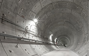
RC segments, mainly manufactured from concrete, are precast concrete products that are a vital part of shield tunneling methods. In this method, RC segments are installed to line the walls of a tunnel as it is being bored by a shield machine.
Necessity of Dimensional Measurement of RC Segments
RC segments are made from reinforced concrete (RC) that incorporates reinforcing steel bars or prestressed concrete (PC).
PC products have higher strength against tensile forces than RC. PC is less likely to crack than RC, which allows for manufacturing of segments with higher watertightness.
High strength is required for RC segments to protect tunnels from the large pressures generated by earth and sand, groundwater, and other materials, so strict dimensional accuracy is required not only for the overall shape of each segment but also their joints and seal grooves.
Impact of Dimensional Errors in RC Segments
A tunnel is segmented into cross-sections at intervals of several meters, and each segment is lined with a ring formed by joining RC segments. The segments are manufactured in shapes divided in the radial direction to facilitate transportation and assembly. During assembly, the rings are connected to line the entire length of the tunnel. The number of segments that constitute a ring is proportional to the diameter of the tunnel. Enormous numbers of segments are used for tunnels, so even small dimensional errors in a segment can cause large deviations after construction.
If errors occur during construction, a lot of work is required to correct them, and any resulting joint failures can reduce strength and waterproof properties. Therefore, dimensional measurement of RC segments is important and needs to be strictly controlled.
Dimensional Measurement of RC Segments
Unlike concrete that is cast on-site, precast RC segments may be deformed not only during manufacturing processes but also under the forces generated during construction. The quality of the entire construction can be enhanced by measuring the deformation to determine whether it is within tolerances.
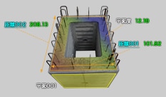
Dimensional measurement points
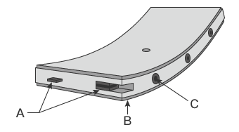
- A
- Segment joint
- B
- Water sealing groove
- C
- Ring joint
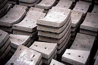
In addition to measuring the overall shape of RC segments, such as width, length, radius, warpage, curvature, twisting, and arc length, the dimensions and shapes of segment joints, ring joints, and even water sealing grooves are important measurement items. Accuracy of RC segments is strictly inspected to ensure smooth assembly at construction sites because tolerances are as tight as 4 mm (0.1575″) even for rings with dimeters exceeding 15 m (49.2′).
There are many RC segment shapes, such as flat and box types, and there are also various types of joints and sealing grooves. This section explains typical flat-type RC segments as an example.
Overall segment shape
The width of segments is increasing to improve the waterproof properties of tunnels, reduce the need for metal joints and sealing materials, and reduce the assembly time required per unit length of tunnel. Larger segment widths increase the weight of segments and the earth pressure applied to each ring, consequently increasing the shearing forces applied to the ring joints. This decreases durability against compressive stress, making it easier for segments to be affected by cracks, chips, and strain. In addition to the overall shape of each segment before assembly, the shape of assembled rings is an essential measurement element.
Segment joint
Segment joints, which connect each segment to its neighboring segments, include tightening joints that use nuts, bolts, and washers, bolt insertion joints, and wedge-shaped metal fitting joints. The most commonly used type of joint for RC segments is the tightening type, which uses nuts, bolts (direct-mounting type), and washers. The bolts used for this type are mounted on joint plates and the positions and angles of internal threads and external threads of the bolts are important measurement points.
Prestressed and precast concrete (P&PC) segments basically have no joints that give tensile strength to segments, such as bolts, because prestressed concrete can be placed between segments and between rings.
Ring joint
For key lock (KL) segments, a type of RC segment, the accuracy of the cushioning keys that join rings is important. The cushioning keys are arc-shaped concavities and convexities with different curvature values. These keys are arranged on the entire circumference of the ring joint and disperse stress radially. If the dimensional accuracy of cushioning keys is low, the strength against shearing forces will be insufficient. This then allows stress to concentrate on joints and their surrounding areas which causes cracking. The degree of stress concentration tends to be especially high on ring joints and their surrounding areas and low at the center of the segment width, so dimensional measurement of the joints is very important.
Water sealing groove
If the dimensional accuracy of water sealing grooves is low, stress is applied to the groove surfaces that contact sealing materials, causing their edges to chip or crack. Inaccurate dimensions of water sealing grooves may even damage assembled segment edges, especially if sealing material that swells in water is used, due to effects of expansion pressure and other factors. For these reasons, the position, dimensions, and shape of water sealing grooves need to be measured with the shape and type of sealing materials taken into consideration.
Covering depth
Covering depth is the depth from the concrete surface to the surface of the reinforcing steel bars embedded in the concrete and has a major effect on corrosion resistance of the reinforcing steel bars. If covering depth is not sufficient, water enters the concrete when it neutralizes or cracks and causes the reinforcing steel bars to rust. Rusted reinforcing steel bars do not provide the designed strength. Covering depth is specified by the Building Standards Act and the Japanese Architectural Standard Specification for Reinforced Concrete and other standards released by the Architectural Institute of Japan. The specified depth differs according to what part of a structure it is used for.
Problems of Dimensional Measurement of RC Segments and Their Solutions
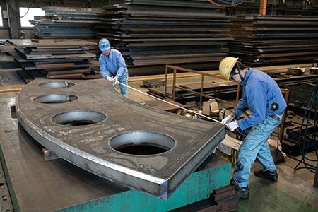
For precast parts such as RC segments, it is important not just to perform dimensional measurements of finished products but also to measure installation angles during construction. Conventionally, these measurements were performed with tape measures and theodolites, and errors during construction were corrected by inserting shims. However, measurement and adjustment took a long time, resulting in longer construction periods. Also, it is not possible to directly measure 3D shapes with hand tools such as tape measures and calipers. Therefore, the dimensions of 3D shapes were indirectly obtained with calculations from the values of the measurable points. The need to perform these calculations is the fundamental problem with this conventional method.
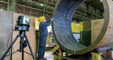
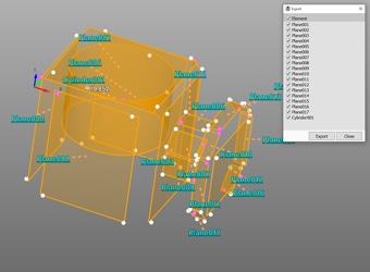
To solve these problems, the latest CMMs are used in an increasing number of cases. KEYENCE’s Wide Area Coordinate Measuring Machine WM Series enables high-accuracy measurement of large-scale targets such as RC segments with the wireless probe. Even recessed areas of workpieces can be reached with no movement restrictions within the measurement range, which allows for single-person measurements with the simple operation of touching targets with the probe. Unlike measurements using measuring instruments such as calipers, tape measures, and theodolites, results do not vary, enabling quantitative measurement.
Optimization of dimensional measurement of large workpieces, on-site assurance of construction accuracy
Large-scale RC segments are usually measured by two people using tape measures or calipers. Additionally, the large number of measurement points makes these measurements require a lot of work.
With the WM Series, it is possible for a single person to easily measure the dimensions of large products with lengths of several meters. Additionally, the wireless probe eliminates movement restrictions, enabling measurement of recessed areas of workpieces. It is possible to measure the bolt pitch and water sealing groove shape of segment joints as well as the overall segment shape. Additionally, the WM Series is portable and thus can meet the need to measure 3D work accuracy on-site, which is impossible with ordinary CMMs.
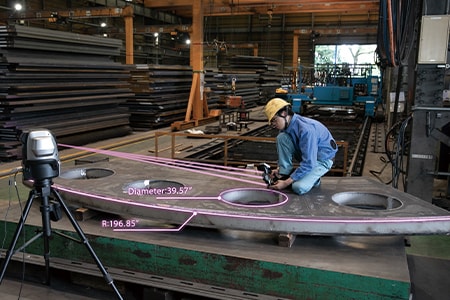

Measurement of large radius and arc length, control of warpage and curvature
It is difficult to measure products with a large radius and arc length with tape measures or calipers. Additionally, it is not possible to measure warpage or curvature accurately because they need to be calculated from measured values at multiple points.
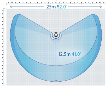
With the WM Series, even workpieces like these can be measured easily. It is possible for a single person to easily measure the radius, arc length, and even 3D measurement items, such as cut angles, by simply touching the points to measure with the handheld probe in an area up to 25 m (82.0′). Also, the height differences of warpage and curvature can be displayed with color maps, allowing surface conditions to be checked at a glance. These advantages make it possible to evaluate joints for issues before assembly and for risks during assembly.
Measurement of Precast Concrete Products and Molds
Each segment needs to be joined with another segment or other parts with high accuracy to produce precast concrete products. The molds used to produce precast concrete must be checked for deterioration because they play a major role in dimensional accuracy. To improve the quality of precast concrete products and decrease the defect rate after assembly, it is important to accurately control mold dimensions and measure the dimensions of finished precast concrete products.
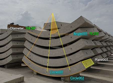
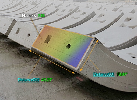
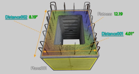
Flatness and wire pitch measurements of joint surfaces
Flatness is measured to determine the accuracy of joint surfaces between segments and rings. It is also necessary to accurately control the pitch of the wires used to join segments with other parts, because the accuracy greatly affects the strength of joints.
When the flatness is checked using tape measures or calipers, multiple points are measured. This checking method is not truly accurate because defective dimensions in unmeasured areas are overlooked. This method is also not efficient because it requires two people and takes a long time.
The WM Series enables easy flatness measurement by simply touching measurement points with the wireless probe and visual check of height differences using the color map display function. It also enables measurements of 3D elements, such as diagonal dimensions and plane angles, in addition to simple linear distances.
Mold measurement
Precast concrete products are formed by pouring concrete into a mold and applying vibration to it to clump and consolidate its particles.
The molds deform over the course of forming many products due to vibration, stress, and friction from the concrete generated during compaction. When molds deform, the dimensions change and cause dimensional defects in products. Measuring mold dimensions during assembly can prevent the release of defective products. However, large molds have many measurement points. Measuring these dimensions using hand tools, such as tape measures, takes a long time and at least two people.
With the WM Series, even large molds can be measured with the simple operation of touching points to measure with the wireless probe. It, of course, enables single-person measurement, dramatically reducing the measurement time required with conventional methods.
Statistical Analysis and Inspection Report Issuance
To control product quality, it is important to control dimensional accuracy and process capabilities. It is necessary to establish systems in which measurement results are digitally acquired and saved according to predetermined rules and systems. Pictures of measurement points need to be managed with links to the corresponding measurement results.
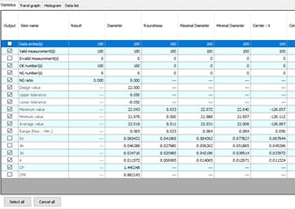
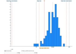
Statistical value check and quality control
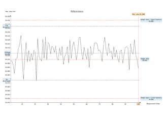
To control the quality of concrete segment products, the following key statistical values are required: pass/fail counts, maximum value, minimum value, average, σ, 3σ, 6σ, and Cpk. Additionally, trend graphs, which indicate changes in statistical values, and histograms, which indicate variations, are important tools for product symptom management. Information from these graphs is vital to understanding the deterioration of molds and manufacturing concrete segments with stable quality.
Issuing inspection reports
Including measured values and photographs of the measurement points in inspection reports makes the measurement situation very clear. These reports also greatly contribute to the simplification of confirmation work during delivery and acceptance of products.
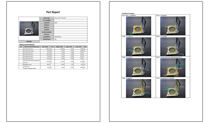
The WM Series automatically saves measurement results to its hard disk. Data required for quality control is automatically extracted from saved data, which makes it easy to check each statistical value. It can also automatically convert measurement results into inspection reports. Photographs can be included in inspection reports, making them easy to understand. The reports use the rich text format (RTF) is used, so they can be edited easily.
Optimization of Dimensional Measurement of Precast Concrete
The WM Series enables accurate single-person measurement of the shape of RC segments with the simple operation of touching targets with the wireless probe. The WM Series also has the many advantages listed below.
- High-accuracy measurement over a large area
- A wide measurement range up to 25 m (82.0′) can be measured with high accuracy. The WM Series is equipped with a navigation measurement mode, which enables measurement at the same point according to a memorized measurement procedure, allowing anyone to obtain the same measurement data.

- The portable body can be placed on-site
- The main unit can be carried around on the cart. The WM Series can be brought into worksites and immediately measure the status of work.
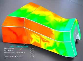
- Check with 3D CAD data
- Comparison measurements are possible between a part being measured and a shape imported from a 3D CAD file. The points of difference between the part and the 3D CAD data can be displayed as a color map. This allows for measurement of free-form curved surfaces and profile tolerances.
- Measurement results can be output as 3D models
- The measured elements can be exported as a STEP/IGES file. 3D CAD data can be created on the basis of the measurement results of an actual product even if no drawing is available.
The WM Series provides powerful support for not just shape measurements of the parts of RC segments and rings after installation, but also for data analysis and inspection report creation. It dramatically improves the efficiency of manufacturing RC segments and of the work indispensable for shield construction.
