3D Optical Profilometers
A Measurement Method That Solves Problems in Coplanarity Inspection
-
Tags:
- Electronic Devices , Stamping
With advances in electronic control of vehicles, and with the increasingly smaller sizes of products such as smartphones and wearable devices, there are growing requirements for smaller sizes and higher mounting density for the electronic components which are used in such products.
At the same time, the smaller sizes and increasingly dense mounting of electronic devices means that even a small load can result in a failure due to lifting at the connections of the mounting boards and surface mounted devices (SMD). In addition to smaller sizes, higher connection quality is required for SMDs, connector pins, and other components that are used in IC chips and other semiconductor packages, particularly those used in automobiles or aircraft because any failure could put human lives at risk. For this reason, coplanarity inspection is important.
This page explains basic knowledge and measurement methods of coplanarity for the connections of leads, pins, balls, and other parts that are closely related to the mounting quality of electronic devices. It also introduces problems with these measurement methods, and the latest solution to these problems.
Coplanarity
Coplanarity refers to a property or state in which multiple points exist on the same plane. Coplanarity of electronic components such as SMDs and connectors indicates the maximum value of the difference between the highest point and lowest point among multiple contacts. Such contacts include the contact pins of pin grid arrays (PGAs), solder balls of ball grid arrays (BGAs), and connector pins. Coplanarity can also be expressed as surface uniformity or terminal flatness.
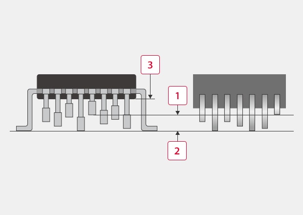
Coplanarity of PGA pins (left) and connector pins (right)
For example, when SMDs are mounted on a PCB using a completely flat PCB surface as the reference line, the allowable coplanarity value is defined as the tolerance for the maximum gap between the board surface and the multiple contact points of the pins or solder balls. Standoff is a different element that is easily confused with coplanarity. Standoff indicates the distance between the board mounting surface and the bottom surface of a molded device package.
-
1Coplanarity
-
2Reference line
-
3Standoff
Importance of Coplanarity Measurement and Its Effect on Quality
Any gap exceeding the allowable range (tolerance) at contacts with electronic components can cause problems such as connection failures of electronic devices mounted on boards, contact failures of connectors, or connection failures caused by even a slight load during use.
Measuring and inspecting the coplanarity of electronic component connections such as pins, solder balls, and leads can ensure the quality of parts and assembly, as well as reliability in the market after shipment.
Loads on PCBs and SMDs can cause problems such as cracking of the package. Loads also causes lifting of soldered connections and can create small air inlets in plastic parts, leading to internal corrosion.
Contact parts such as pins, solder balls, and leads are exposed to mechanical and thermal stress during manufacturing processes such as pressing, plastic working, forging, cutting, and potting with resin. Therefore, in order to check that parts were manufactured in the shape specified in the drawings, simply calculating the two-dimensional shape is not sufficient to determine coplanarity. Three dimensional changes in shape such as inclination and bending can also cause variation in pitch and coplanarity, resulting in connection failures.
Measurement Difficulties
This section explains the conventional methods of measuring coplanarity and the common problems experienced.
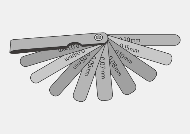
Measurement Difficulties - Feeler Gauge
A feeler gauge is a tool used to measure the dimensions of a gap by inserting a thin metal plate into the gap. It is also known as a clearance gauge. Typical feeler gauges can measure small gaps ranging from 0.03 mm (0.001″) to 1.00 mm (0.03″).
Measurement using feeler gauges involves the following problems.
- This method involves large variation in the measured values, and if the tool is not handled carefully, it can damage the electronic components. Measurement and inspection require much time and effort, making it difficult to inspect all parts.
- Because measurement results cannot be output as data, operators must input values manually in order to create reports and perform trend analysis.
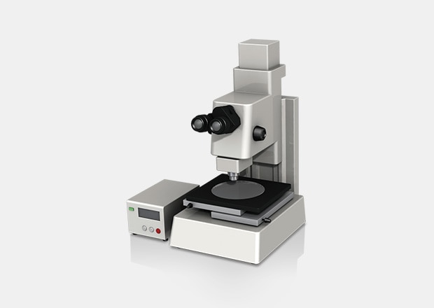
Measurement Difficulties - Microscope
Measuring microscopes were developed for measurement purposes based on the existing principles of metallurgical and stereoscopic microscopes, and can exhibit measurement accuracy of around 1 μm (0.00003″). Measuring microscopes also allow users to check the amount of stage movement numerically.
However, measurement using microscopes involves the following problems.
- There is no freedom in the measurement directions. To measure multiple pins arranged in three dimensions, a time-consuming process is required to turn the workpiece so it faces different directions and fix it in place using a jig each time.
- Dimensions need to be checked visually, which results in measurement error depending on the operator.
Coplanarity Measurement Solutions
Much time and effort is required for coplanarity measurement and inspection using ordinary measuring instruments and microscopes. These instruments also have the serious problem of variation in measured values. It is also difficult to measure miniaturized electronic devices with contact-type measuring instruments, and such instruments may even damage the targets during measurement.
To resolve these measurement problems, KEYENCE has developed the Wide-Area Optical Profiler VR-6000 Series.
The VR-6000 Series accurately captures the 3D shape of the entire target surface without contacting the object. The VR-6000 Series does not require special fixturing or subjective decisions to be made, enabling accurate measurements to be performed by any operator. This section introduces some specific advantages of the VR-6000 Series.
Coplanarity measurement of multiple leads using the VR-6000 Series
Advantage 1: Quick and Easy Shape Measurement
The VR-6000 Series requires only the simple step of placing the workpiece on the stage. It then automatically moves the stage to position the target, and instantaneously scans its shape. Variation in measurement results does not occur regardless of what part of the target is measured.
With no need for advanced fixturing, the VR-6000 Series can measure the coplanarity and profile of multiple pins, leads, and solder balls in a single measurement, significantly shortening the time required for measurement.
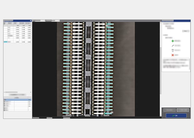
Advantage 2: Visualization of 3D Shapes
The VR-6000 Series scans the 3D shape of the entire target surface and creates a 3D model that is easy to understand.
For example, it captures differences in height caused by bending or inclination among large numbers of pins and leads arranged side by side in a single measurement, displaying these differences in a 3D image using different colors. This advantage allows users to specifically understand which parts on the target are exceeding tolerances and which shapes are causing problems, helping to identify the causes of defects and prevent their recurrence. Using these data images, users can also create easy-to-understand reports and share information with other divisions.
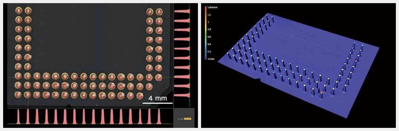
Coplanarity measurement of PGA pins using the VR-6000 Series
Summary: Dramatic Improvement and Higher Efficiency for Coplanarity Measurements
With the VR-6000 Series, the 3D shape of the entire target can be instantaneously measured by non-contact scanning. In addition to solving the problems of conventional measurement, the VR-6000 Series can dramatically improve work efficiency in coplanarity measurement of electronic components.
- The non-contact measurement applies no measurement pressure to sensitive electronic components, and therefore there is no risk of damaging the measurement target.
- Simply place the target on the stage and the VR-6000 Series automatically performs positioning adjustments before measurement. This eliminates variations in measured values, and enables swift inspection.
- Coplanarity of large numbers of pins, leads, and solder balls arranged side by side can be measured instantaneously.
- 3D data can be visualized with a height-color map, enabling creation of reports that clearly communicate problems and defects.
The VR-6000 Series solves the problems in conventional measurement of electronic components, and measures the entire surface of the target in an instant. It can support the current need for smaller and denser electronic components, while also significantly improving work efficiency during measurement and report creation.

Related Downloads

Related Products
Applications
- Chamfer
- Corner Rounding / Fillet
- Bending Radius
- Corner Relief / Undercut
- Taper
- Shank Thread / Underhead Shape
- Tooth Thickness
- Rake Angle
- Metal Burr
- Plastic Burr
- Shear Droop
- Sink Mark
- Solder Fillet
- Weld Bead
- Lead Frame (Lead Lifting)
- Warpage
- Flatness
- Coplanarity
- Surface Waviness
- Surface Area
- Wear
- Bearing Wear
- Die Wear
